Ee “audio clock and, Serial digital i/o upgrade installation, Audio clock and sharcnet cabling – Grass Valley Profile Serial Digital User Manual
Page 30
Serial Digital I/O Upgrade Installation
22
Serial Digital I/O Upgrade Installation
Audio Clock and Sharcnet Cabling
This example shows the external audio clock and Sharcnet cabling necessary for
two serial digital I/O boards (two channels each for a total of four channels) used
with an ASPB. The cable connections are listed in Table 5 and shown in Figure 5.
Each ASPB provides input of four external audio clock signals, one to each
Audio 1 through Audio 4 bank, where each bank consists of four audio channels.
ASPB Audio 1 through Audio 4 connectors begin closest to the rear panel and go
toward the front panel.
In general, the video board in the lowest numbered slot must provide the audio
clock signal to the Audio 1 bank, then the video board in the next lowest numbered
slot must provide the audio clock signal to the Audio 2 bank, and so forth. For
example, if you have video boards in slots J5 and J11, the audio clock signal from
the video board in J5 must be connected to Audio 1 on the ASPB and the audio
clock signal from the video board in slot J11 must be connected to Audio 2 on the
ASPB. If there are no available clock connectors on the ASPB, video inputs on the
unclocked board must be synchronous with a clocked input.
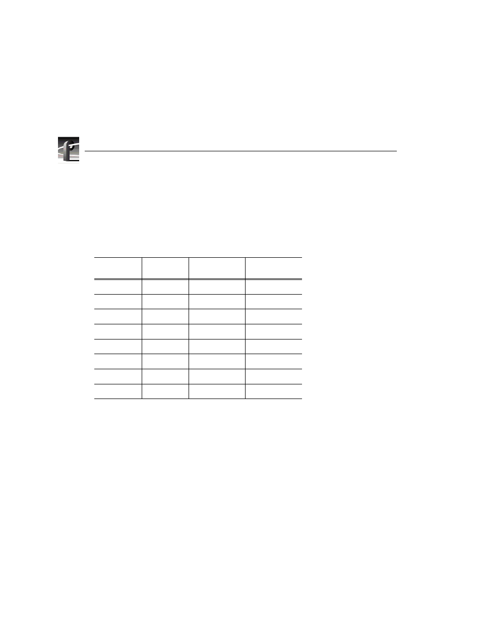
Table 5. PDR200 cabling for two serial digital I/O boards and an ASPB
Cable Type
Serial Digital
I/O Slot
From Serial
Digital I/O
To ASPB
Sharcnet
J15
Sharcnet A
Sharcnet 1
Sharcnet
J14
Sharcnet A
Sharcnet 2
Sharcnet
J15
Sharcnet B
Sharcnet 3
Sharcnet
J14
Sharcnet B
Sharcnet 4
Audio clock
J14
Channel A
Audio 1
Audio clock
J14
Channel B
Audio 2
Audio clock
J15
Channel A
Audio 3
Audio clock
J15
Channel B
Audio 4