Grass Valley Profile Serial Digital User Manual
Page 28
Serial Digital I/O Upgrade Installation
20
Serial Digital I/O Upgrade Installation
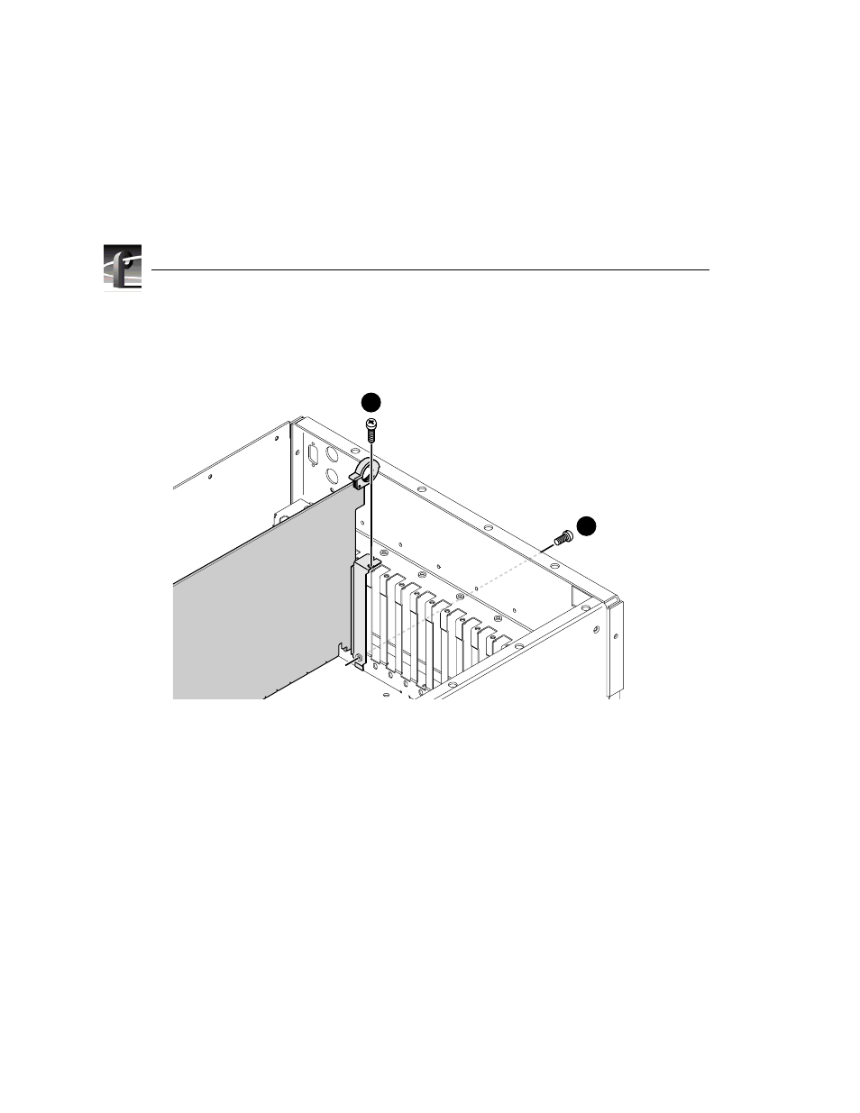
Figure 4. Screw locations for board mounting bracket
4. Install the blank circuit board brackets (if necessary) in the empty board slots
on the rear panel.
5. Connect the audio clock and Sharcnet cables (see “Audio Clock and
Sharcnet Cabling” on page 22).
6. Use the Torx tool with the T10 tip to reinstall the rear board hold-down
bracket (see Figure 2).
7. If necessary, reconfigure the front board hold-down bracket, moving or
removing a short board extension, and use the Torx tool with the T10 tip to
reinstall the front board hold-down bracket (see Figure 2).
8. Use the Torx tool with the T10 tip to reinstall the rear top cover with the
screws previously removed.
9. Use the Torx tool with the T10 and T15 tips to reinstall the front top cover
with the screws previously removed.
9040-13
1
2
- LDK 5302 (24 pages)
- SFP Optical Converters (18 pages)
- 2000GEN (22 pages)
- 2011RDA (28 pages)
- 2010RDA-16 (28 pages)
- 2000NET v3.2.2 (72 pages)
- 2000NET v3.1 (68 pages)
- 2020DAC D-To-A (30 pages)
- 2000NET v4.0.0 (92 pages)
- 2020ADC A-To-D (32 pages)
- 2030RDA (36 pages)
- 2031RDA-SM (38 pages)
- 2041EDA (20 pages)
- 2040RDA (24 pages)
- 2041RDA (24 pages)
- 2042EDA (26 pages)
- 2090MDC (30 pages)
- 2040RDA-FR (52 pages)
- LDK 4021 (22 pages)
- 3DX-3901 (38 pages)
- LDK 4420 (82 pages)
- LDK 5307 (40 pages)
- Maestro Master Control Installation v.1.5.1 (455 pages)
- Maestro Master Control Installation v.1.5.1 (428 pages)
- 7600REF Installation (16 pages)
- 7600REF (84 pages)
- 8900FSS (18 pages)
- 8900GEN-SM (50 pages)
- 8900NET v.4.3.0 (108 pages)
- Safety Summary (17 pages)
- 8900NET v.4.0.0 (94 pages)
- 8906 (34 pages)
- 8911 (16 pages)
- 8900NET v.3.2.2 (78 pages)
- 8914 (18 pages)
- 8912RDA-D (20 pages)
- 8916 (26 pages)
- 8910ADA-SR (58 pages)
- 8920ADC v.2.0 (28 pages)
- 8920ADC v.2.0.1A (40 pages)
- 8920DAC (28 pages)
- 8920DMX (30 pages)
- 8920ADT (36 pages)
- 8920MUX (50 pages)
- 8921ADT (58 pages)