Remove the circuit board retainers, Install the analog composite output circuit board – Grass Valley PDR 100 Analog Composite Ou User Manual
Page 16
Analog Composite Output Installation
4
Analog Composite Output Installation
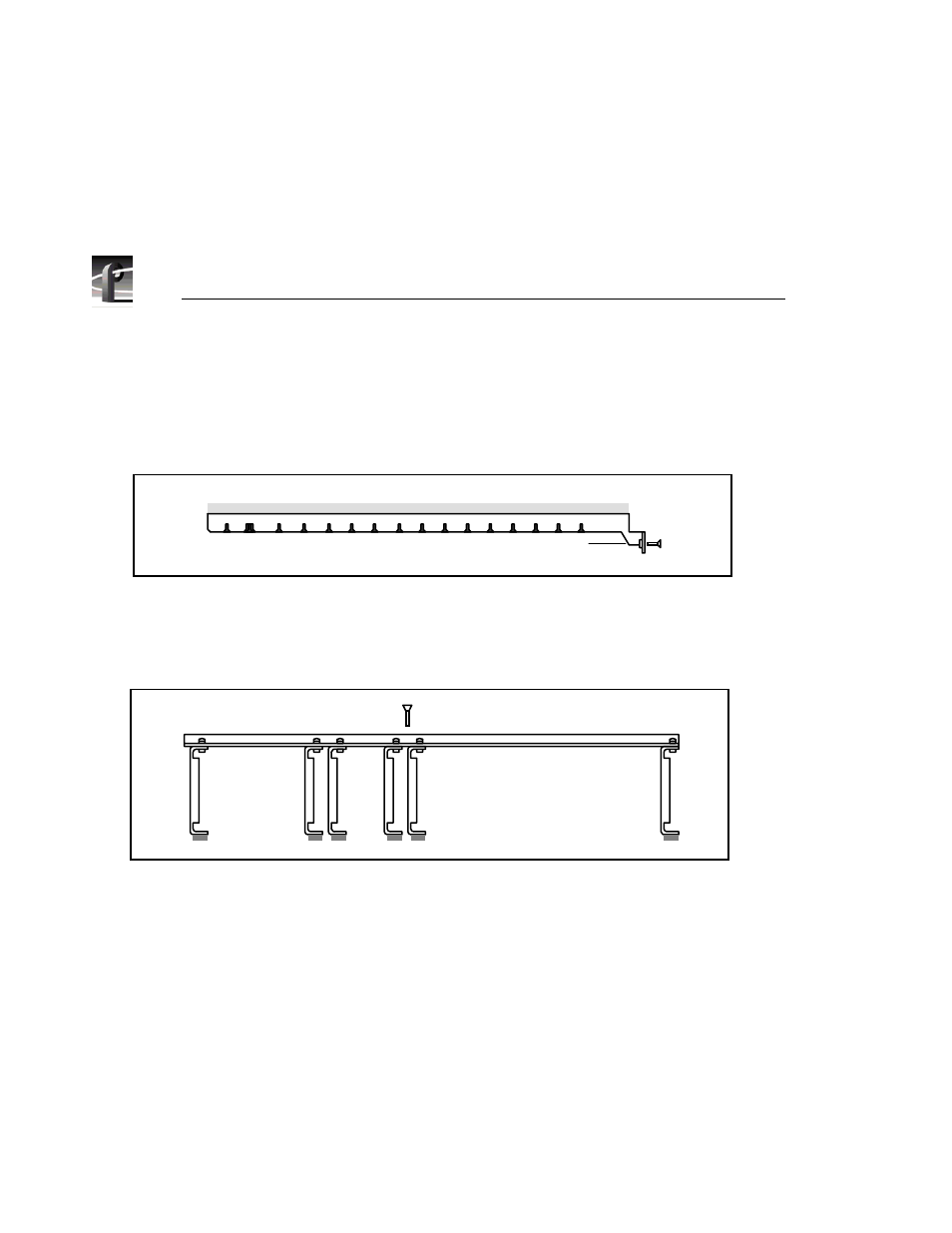
Remove the Circuit Board Retainers
1. Remove the screw that attaches the tall circuit board retainer to the left side
of the chassis and pull the retainer straight up.
Figure 2. Retainer for Tall Circuit Boards
2. Remove the retainer for the short circuit boards. Remove the attaching screw
located in the middle of the retainer. Lift the retainer straight out.
Figure 3. Retainer for Short Circuit Boards
Install the Analog Composite Output Circuit Board
1. Select slot J11 or J12 for this application. Remove any circuit board that may
be installed in this location.
>>> CAUTION. Do not exert any force on the rear panel-connectors when
removing or installing circuit boards in the card slots.
Two screws hold the circuit board in the card slot, one accessible from the top
of the PDR 100 and the other accessible from the rear. Both screws must be
removed before the circuit board can be removed.
Rear View
9041-16
Rear View
Mounting
Screw
9041-15