System control – Grass Valley Kaleido-MX (1RU) v.7.80 User Manual
Page 25
11
Kaleido-MX (1RU)
Hardware Description & Installation Manual
The following table lists the function of each connector associated with the output heads.
System Control
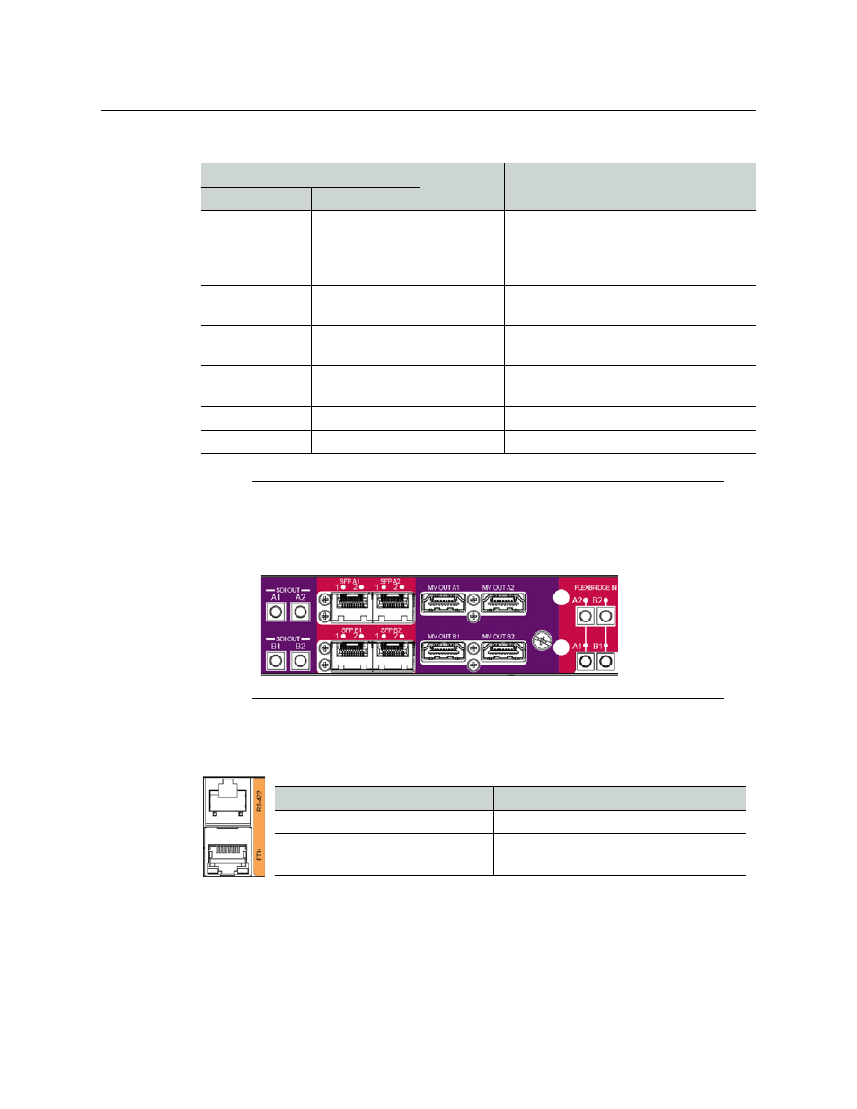
The following table lists the purpose of each connector associated with system control.
Connector label
Connector
type
Function
Head 1
Head 2
MV OUT 1
MV OUT 2
HDMI
High definition connection for the
multiviewer output, which carries audio
and video, and can support resolutions up
to 1920 × 1200 (all progressive scan)
SDI OUT 1
SDI OUT 2
DIN 1.0/2.3
Serial digital HD output signal for
monitoring purposes
ANALOG OUT 1 L ANALOG OUT 2 L WECO
Analog audio output (left channel) to feed
the audio monitoring system
ANALOG OUT 1 R ANALOG OUT 2 R WECO
Analog audio output (right channel) to
feed the audio monitoring system
SFP 1
SFP 2
—
Optional ports. Not yet supported.
FLEXBRIDGE IN 1 FLEXBRIDGE IN 2 DIN 1.0/2.3
Reserved for future expansion
Note:
In the case of the Kaleido-MX (1RU) 16 × 4 model, the two pairs of
connectors associated with output heads A and B are labelled as follows: MV
OUT A1, MV OUT A2, MV OUT B1, MV OUT B2, etc., and this model does not have
analog audio output connectors (see
Kaleido-MX 16 × 1, 16 × 2, and 16 × 4
Output module connectors on Kaleido-MX (1RU) 16 × 4
Connector label
Connector type
Function
ETH
RJ-45
100 Base-T Ethernet connection
RS-422
RJ-45
Connect to an RS-422 (SMPTE ST 207,
EBU-3245) or RS-485 device or network