Rear of the kaleido-mx (1ru) frame – Grass Valley Kaleido-MX (1RU) v.7.80 User Manual
Page 19
5
Kaleido-MX (1RU)
Hardware Description & Installation Manual
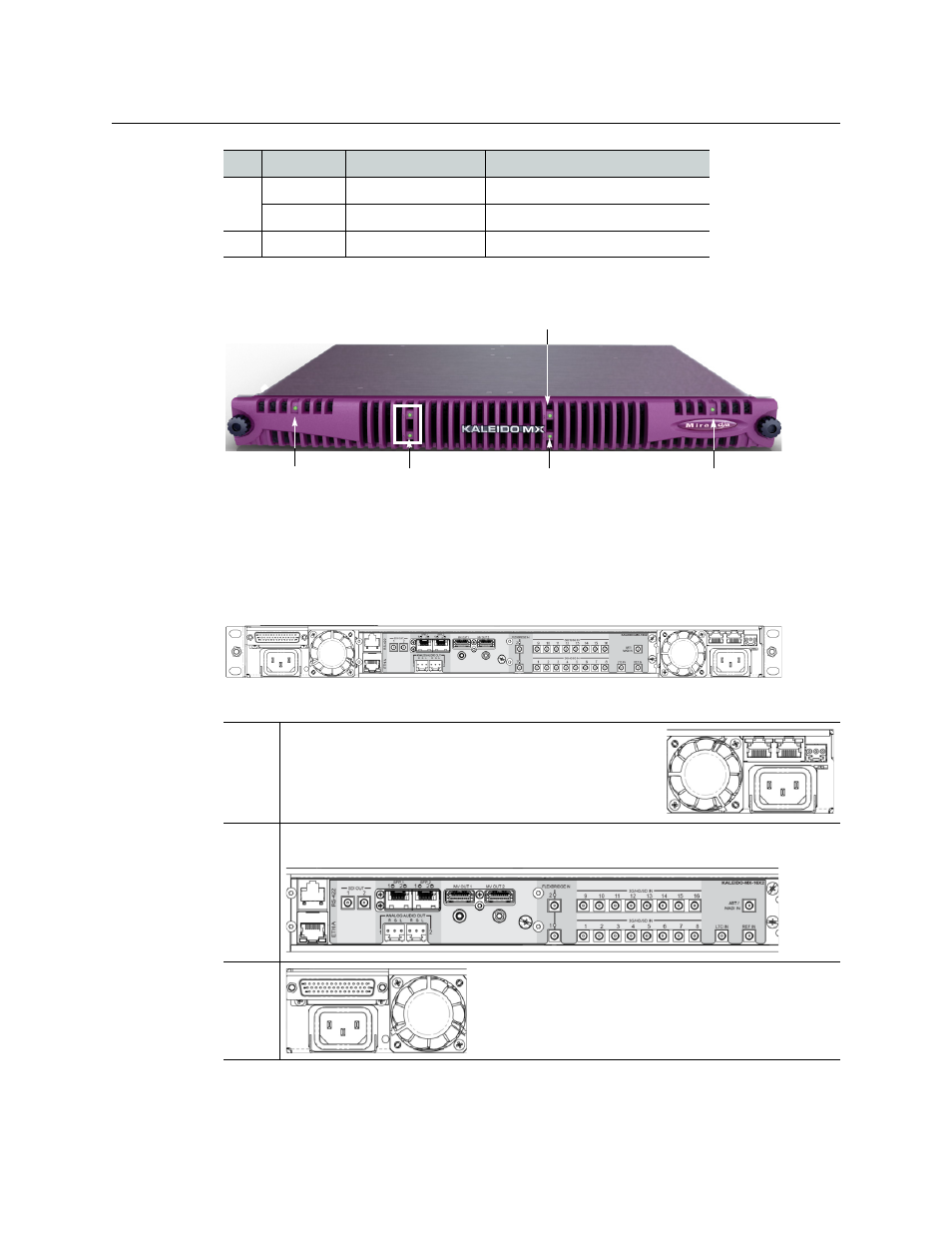
When the frame door is closed, the status LED on each of the cards in the frame is visible via
a light pipe in the door. No other controls or indicators are present.
Rear of the Kaleido-MX (1RU) frame
The rear of the Kaleido-MX (1RU) frame is organized in three sections, matching the front.
Viewed from the back of the frame, the three sections are laid out as follows:
4
Output B
KMX-3901-OUT-D
16 × 4
Input A
KMX-3901-IN-8-D
24 × 2, 24 × 1
5
GPI I/O
GPI-1501
All 1RU configurations
Right
This area contains inputs and outputs for the controller
card: the fan speed control setting switch, a GPI port and
two Ethernet ports. It also contains the power socket for
the power supply located beneath the controller card,
and one of the two frame fans.
Center This area contains the connectors associated with your multiviewer’s input and
output cards.
Left
This area contains the power socket for the power
supply located beneath the GPI-1501 card, and one of
the two frame fans.
Slot Card
Card model
Applies to...
Controller card
status
Input card status
GPI-1501 card status
Output card status
Output card status
(for 16
×
4 model)
Input card status
(for 24
×
2 model)