Installation, Module placement in the 2000 frame – Grass Valley 2041EDA User Manual
Page 8
8
2041EDA Instruction Manual
Installation
Installation
Installation of the 2041EDA module is a process of:
•
Placing the module in a rear frame slot, and
•
Cabling signal ports.
The 2041EDA module can be plugged in and removed from a Kameleon
2000 Series frame with power on. When power is applied to the module,
LED indicators reflect the initialization process (see
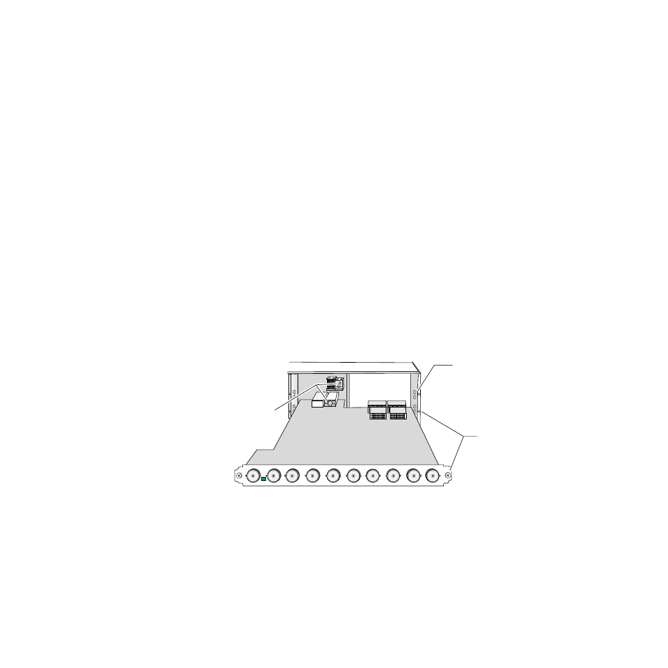
Module Placement in the 2000 Frame
There are twelve rear cell locations in the 3 RU frame to accommodate
either analog or digital modules. The 2041EDA rear module plugs into any
one of the rear slots of the Kameleon 2000 frame.
1.
Install the module by inserting it into any rear slot of the frame as
illustrated in
.
2.
Verify that the module connector seats properly against the midplane.
3.
Secure the module to the rear of the frame with the two screw locks on
either side of the back panel using a crossblade screwdriver.
Figure 1. Installing 2041EDA Module
J10
SIG
IN
J9
J8
J7
J6
J5
J4
J3
J2
2041
EDA
J1
Alignment post
and receptacle
Screw lock
(both sides)
8032_01
2000 frame (rear view)
Board edge guides
(both sides)