Ensemble Designs BrightEye 3 Analog to SDI Converter with TBC and Frame Sync User Manual
Page 5
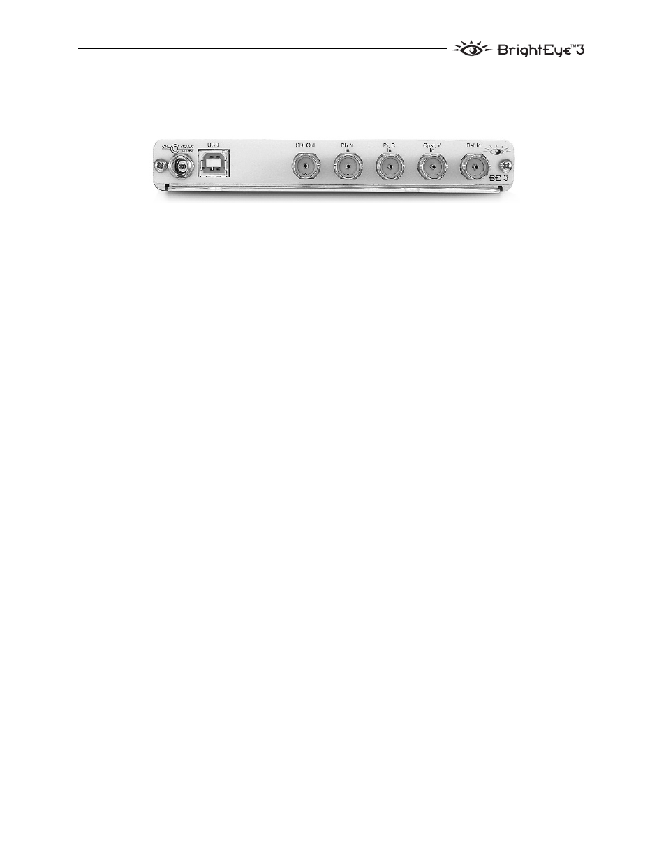
REAR CONNECTORS
All connections to the BrightEye converter are made on the rear of the unit.
Refer to the illustration below.
Power Connection
Connect a modular power supply to the 12 volt DC power input connection on the
far left. Use the locking ring to secure it.
USB Connector
The USB connector is used to provide more comprehensive control, diagnostics,
and upgrades to the unit from a PC or Mac. Use the BrightEye Control applica-
tion included on CD-ROM to make adjustments as described in the OPERATION
section of this user guide.
Input/Output BNCS
There are five rear BNC connectors which are used as follows:
SDI Out
The Serial Digital Component output of the converter is presented on this
connector. This output conforms to the ITU-R 601 standard for serial digital
video, with SMPTE 259M serialization at 270 Mb/s.
Pb In
This is an internally terminated, 75 ohm input for the following:
•
Beta or SMPTE – Pb input
Pr, C In
This is the internally terminated, 75 ohm input for the following format signals:
•
Beta or SMPTE – Pr (Y-R) input
•
S-Video (composite) – C input
BrightEye-5
BrightEye 3 Rear Connectors
- 5130 Digital to Analog Composite Converter with Digital DA (11 pages)
- 5125 Dual Digital Video Distribution Amplifiers (12 pages)
- 7450 HD Protection Switch (43 pages)
- 5420 SD Logo Inserter (26 pages)
- 5410 Dual Sync Generator and Test Signal Generator with HD Tri-Level Sync (42 pages)
- 7925 Dual HD Downconverter (42 pages)
- 5475 Digital Noise Reducer Sub Module for 5470 (32 pages)
- 9110 3G / HD / SD / ASI Reclocking Distribution Amplifier (27 pages)
- 7420 HD/SD Logo Inserter (40 pages)
- 7420 HD/SD Logo Inserter (36 pages)
- 9465 3G Sync Changeover Switch (38 pages)
- 7600 HD/SD Embedder/Disembedder (30 pages)
- 7550 HD Legalizer (42 pages)
- 9550 3G / HD / SD Video Processing Frame Synchronizer (70 pages)
- 7920 HD Downconverter (47 pages)
- 5330 & 6330 Analog to Digital Video Converter and Embedder (76 pages)
- 9455 3G Clean and Quiet Protection Switch (64 pages)
- 4500 ASI and SMPTE 310M Converter and MPEG Transport Processor (32 pages)
- 5140 Analog EQ DA (12 pages)
- 5150 DA for Analog Video, AES and Tri-Level Sync (12 pages)
- 5155 Dual Analog Video, TLS, AES DA (12 pages)
- 9440 Flexible Matrix Router for 3G / HD / SD / ASI (138 pages)
- 5385 Analog Composite to Digital Converter (16 pages)
- 5365 Four Channel Analog to Digital Video Converters and Embedders (24 pages)
- 4110 ASI Distribution Amplifier (11 pages)
- 6030 Video-Reference AES/ Word Clock Generator (15 pages)
- 6040 Tracking Audio Delay (34 pages)
- 7405 HD Test Signal Generator (20 pages)
- 7410 Quad HD Tri-Level Sync Generator (16 pages)
- 6010 Four Channel 24-bit Audio ADC (19 pages)
- 6600 Series Analog Audio DAs and Frame Models 6601, 6601R and Frame 6600 (16 pages)
- 6020 Four Channel 24-bit Audio DAC (26 pages)
- BrightEye 20 Analog and Digital Audio Embedder or Disembedder (21 pages)
- 9670 Audio Automatic Gain and Loudness Control and 9690 Audio Compliance and Monitoring Software (18 pages)
- 9670 Audio Automatic Gain and Loudness Control and 9690 Audio Compliance and Monitoring Software (32 pages)
- 7400 HD/SD Test Signal and Sync Pulse Generator (82 pages)
- BrightEye 46 3G/HD/SD/ASI Electrical to Optical Converter (16 pages)
- BrightEye 70 HD/SD AES Embedder/Disembedder (26 pages)
- BrightEye 71-F HD/SD 8 Channel Analog Audio Embedder/Disembedder (27 pages)
- BrightEye 81-F Optical to HDMI and 3G / HD / SD SDI Electrical Converter (27 pages)
- BrightEye 72-F SDI to HDMI Converter, Color Corrector and Broadcast Confidence Monitor (40 pages)
- BrightEye NXT 430 and NXT 415 Compact Video Routers (132 pages)
- BrightEye 92-A HD Downconverter with Analog Audio (41 pages)
- BrightEye 83-F HDMI to Optical and Electrical 3G / HD / SD SDI Converter (26 pages)