Ensemble Designs 7405 HD Test Signal Generator User Manual
Page 7
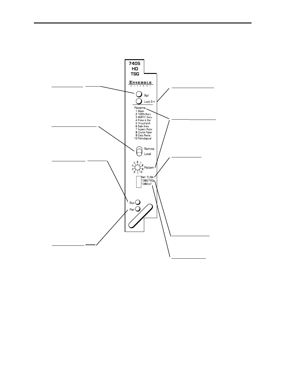
Front Panel Controls and Indicators
Each front edge indicator and switch setting is shown in the diagram below:
7405-7
Remote/Local switch:
Set to the mode you
will be using.
Pwr green LED:
Indicates the presence (ON) or
absence (OFF) of power (+5V).
Run green LED:
OFF:
A power fault or halted CPU.
ON:
A halted CPU.
FAST BLINK:
CPU Run error.
SLOW BLINK:
System OK. (If SPI control is
active from the main frame
System Control Module, all
Run indicators will be syn-
chronized.).
Ref green LED:
On when selected input
reference is present and
locked to output. Off when
unlocked.
Model 7405 HD Test Signal Generator
Lock Error red LED:
On when the output is
not locked to the
selected reference.
Ref (Reference)
TL/Blk switch:
Set the reference type for TL, Tri-
Level, (left) or Blk, SD Composite,
(right). The reference source is the
Ref In BNC on the rear of the 7405.
Note: For correct locking in TL, the
Tri-level reference connected must
match the HD output standard.
When Blk (SD Composite ) is
selected, the line rate of the HD
output will automatically match the
reference.
1080/720p switch:
Select output standard for either
1080 (left) or 720p (right).
1080i/sF switch:
When switch above is set for 1080,
set the switch for 1080i (left) or
1080sF (right).
Note: 1080p is not available in
Local mode.
Pattern select switch:
Select one of the HD test signal
patterns listed with the rotary
switch.