Ensemble Designs 7405 HD Test Signal Generator User Manual
Page 4
INSTALLATION
Plug the 7405 module into any one of the slots in the 1 RU or 3 RU frame. Install the
plastic overlay provided onto the corresponding group of rear BNC connectors associated
with the module location. Note that the plastic overlay has an optional adhesive backing
for securing it to the frame. Use of the adhesive backing is only necessary if you would
like the location to be permanent and is not recommended if you need to change module
locations. This module may be hot-swapped (inserted or removed) without powering down
or disturbing performance of the other modules in the system.
CABLING
Refer to the 3 RU and 1 RU backplane diagrams of the module below for cabling instruc-
tions. Note that unless stated otherwise, the 1 RU cabling explanations are identical to
those given in the 3 RU diagram.
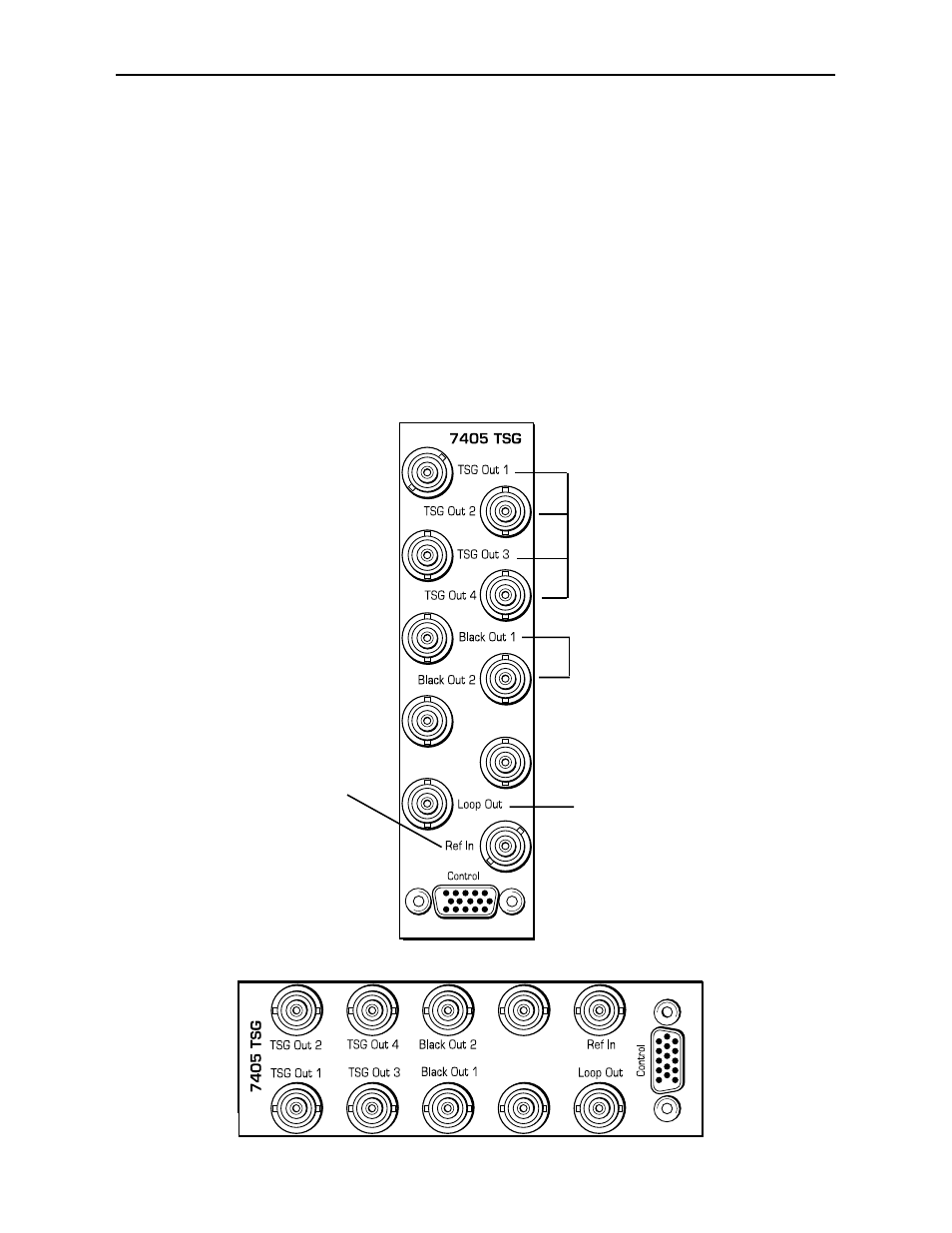
7405-4
Model 7405 HD Test Signal Generator
3 RU Backplane
Connect a Tri Level or
SD Composite (525 or
625) sync reference
signal to the Ref In BNC.
(This input is required
when the module is used
in Local mode.)
Connect the four copies of the
HD test signal on BNCs TSG
OUT 1 – 4 to high definition
destinations.
Connect the two copies of the
Black test signal output on
BNCs Black Out 1-2 to high
definition destinations.
Loop the reference signal
input to other destinations
from the Loop Out BNC.
1 RU Backplane