Eneo AVU-8/2EC User Manual
Page 10
0
Alarm specification
If only one input is activated, that input is switched to ChANNEL A or ChANNEL B and the
buzzer is activated. In ChANNEL A, the ”AUTO” and ”MAN” LEDs flash. The activated alarm
input appears in ChANNEL A. If there is more than one alarm, the display alternates between
the alarm inputs. If ChANNEL B is selected, the point in the LCD display blinks. The alarm
output is activated (switched to GND).
If more than one signal input is activated the alarmed inputs appear sequentially in
ChANNEL A or ChANNEL B.
ChANNEL B is automatically switched from ”sequence” mode to ”single frame” mode if the
ALARM-SINGLE FRAME SWITChING (FRAMES) is activated in the menu.
This function is deactivated if VCR CLOCK is connected.
The alarm dwell time and alarm duration are set in the SET-UP menu. When the ALARM
STOP key is pressed, the alarm of ChANNEL A is manually reset.
If ChANNEL B is set, the alarm automatically resets after a certain time. The LCD display
shows the No. of the alarm input. If there are several alarms the LCD display switches over.
Remote control
Remote control of ChANNEL A is possible if the ”AUTO” (sequential) mode is set. The
automatic sequence is stopped and re-started using key T. If stopped, T is used for
changing the channels manually. The input REMOTE CONTROL must be selected in the
SETUP menu and the alarm must be switched out.
Monitor display
The AVU-8/AL- has a multilingual menu display (English, Italian and German).
The language is set using the menu. The number of the signal input which appears on the
monitor, is shown in the lower right corner of the monitor. When setting, the interval time is
shown in the bottom left corner.
Trouble shooting
If problems occur through earth loops between different video sources and the switcher, the
lid of the device must be removed and GND on K403 (earth lead connection from casing to
base plate) is to be separated from the main plate. The electrical earth of the plate is thus
separated from casing and earth.
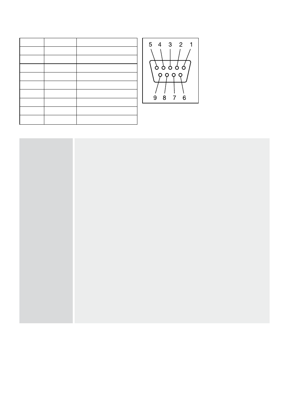
3.6 Connection and pinout of the alarm input/remote control D-9F
PIN No.
ALARM
REMOTE CONTROL
ALARM
T
ALARM
T
3
ALARM 3
n.c.
4
ALARM 4
n.c.
5
ALARM 5
n.c.
6
ALARM 6
n.c.
7
ALARM 7
n.c.
8
ALARM 8
n.c.
9
MASSE
MASSE