3 construction, 1 front panel, 1 leds – ATL Telecom OM25 User Manual
Page 11: 1 status, 2 optical, 3 interface, Construction, Front panel, Leds, Status
11
ATL User Guide
OM25 O
Optical M
Modem
3
3
CONSTRUCTION
The front panel controls have a dual purpose. For normal operation, the LED indicators display
status information and the push buttons are used for applying test loops. These controls can
however, also be used to configure the modems without the need to plug in a VT100 terminal or
PC. To do this, the front panel controls must be enabled for "Full Control" (default setting) and
the unit set to Programming Mode, section 7.
3.1
FRONT PANEL
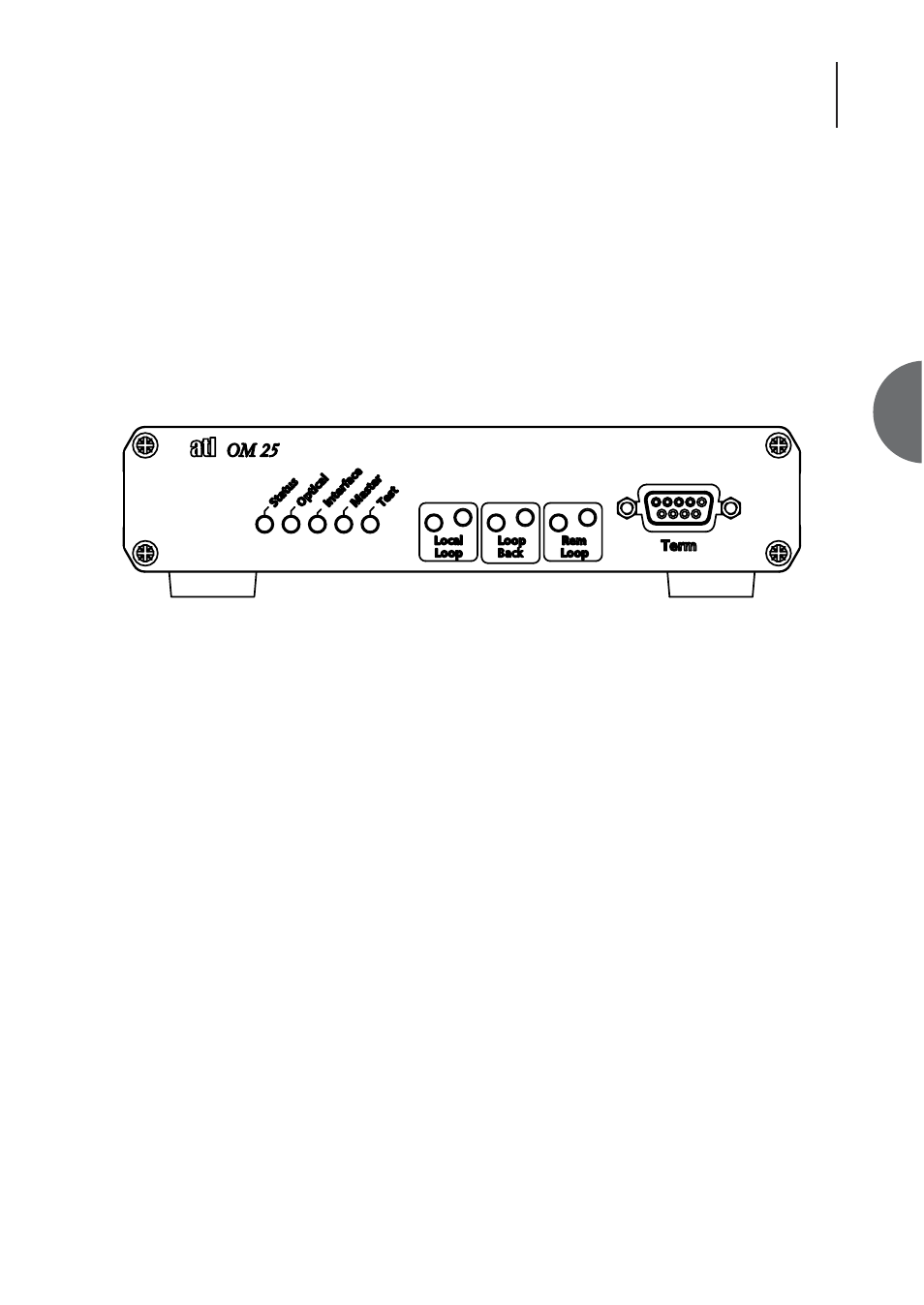
The front panel of the OM25 contains a RS232 9 way D-Type terminal connection, eight status
LEDs and three front panel buttons
Figure 4 Front Panel
3.1.1
LEDS
3.1.1.1
STATUS
Red - An urgent alarm is present in the system.
Amber - A non-urgent alarm is present in the system.
Green - No alarms are present in the system.
3.1.1.2
OPTICAL
Red - An urgent alarm is present on the Optical Port.
Amber - A non-urgent alarm is present on the Optical Port.
Green - No alarms are present on the Optical Port.
3.1.1.3
INTERFACE
Red - An urgent alarm is present on the User Interface.
Amber - A non-urgent alarm is present on the User Interface.
Green - No alarms are present on the User Interface.
In the ‘green’ state the state of the received data (data output from the modem on the user
interface) is indicated. The LED is green for 1’s and off for 0’s.
11