Installation guide – ACTi Outdoor Ready Box on Vertical Pole with Accessory Set User Manual
Page 16
Installation Guide
To connect input devices (DI), map the pins to one of the pin combinations below:
Device
Pin
Mapping Instructions
Digital Input 2
(DI2)
2
DI2
Connect the wires of the one input device to
DI2
(Pin 2)
and
GND
(Pin 4).
4
GND
Digital Input 1
(DI1)
6
DI1
Connect the wires of another input device to
DI1
(Pin 6)
and
GND
(Pin 8).
8
GND
The table below shows the DI/DO connection specifications:
Device
DI
Connection design
TTL - compatible logic levels
Voltage
To trigger (low)
Logic level 0: 0V ~ 0.4V
Normal (high)
Logic level 1: 3.1V ~ 30V
Current
10mA ~ 100mA
DO
Connection design
Transistor (Open Collector)
Voltage & Current
< 24V DC, < 100mA
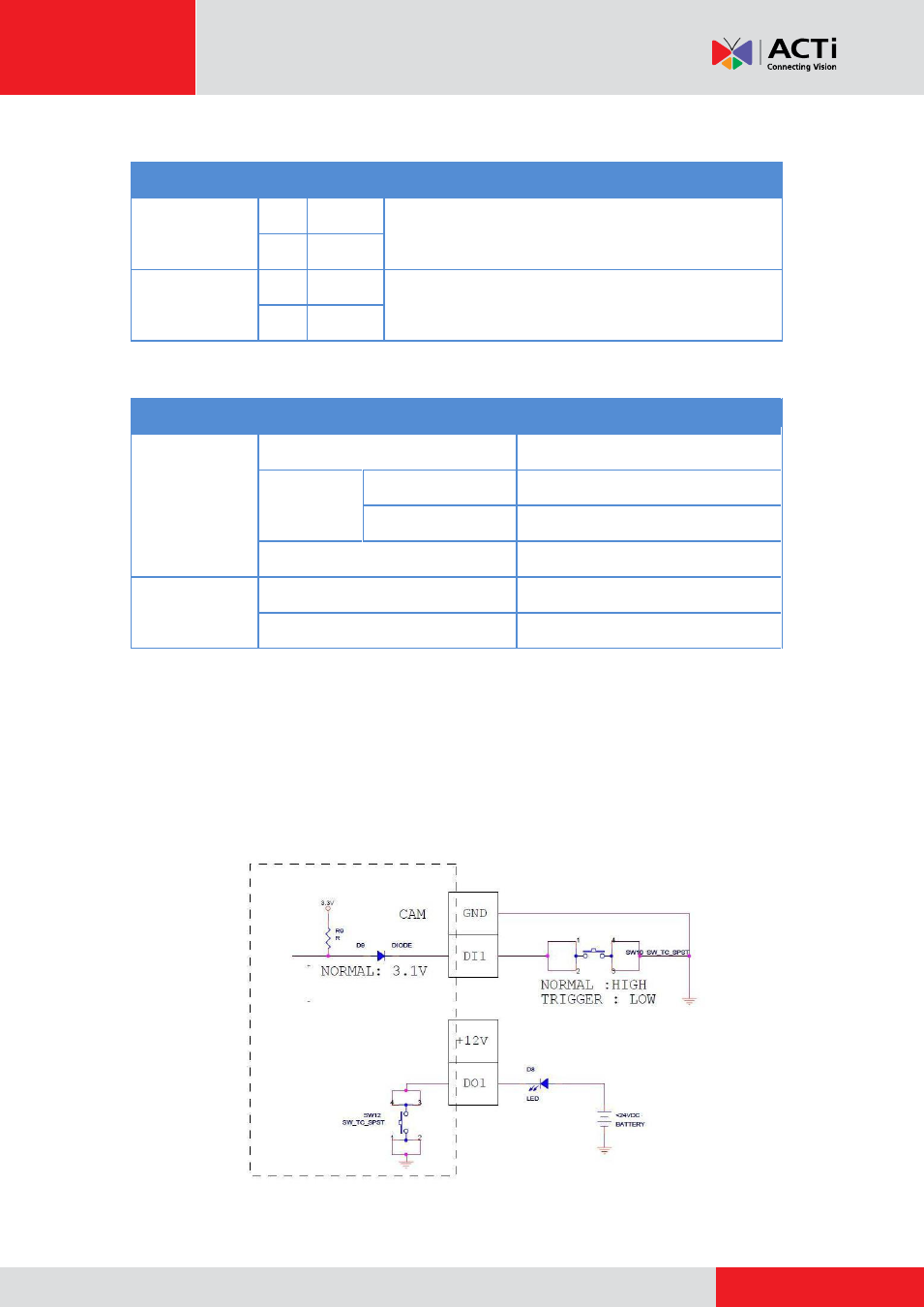
Typical Connection
Based on these specifications, if the DI device has a voltage of 0V ~ 30V or the DO device has a
voltage of < 24V (<100mA), then the camera can supply internal power to these devices and
there is no need to connect the DI/DO device to an external power source.
In this case, wire connection to Pins 1 to 4. Use the
GND
and
DI2
pins to connect a DI device and
use the
12V
and
DO2
pins to connect a DO device. See wiring scheme below:
Consequently, to connect a second DI or DO device, wire the connection to Pins 5 to 8.