Encoder hardware manual – ACTi V31 User Manual
Page 17
Encoder Hardware Manual
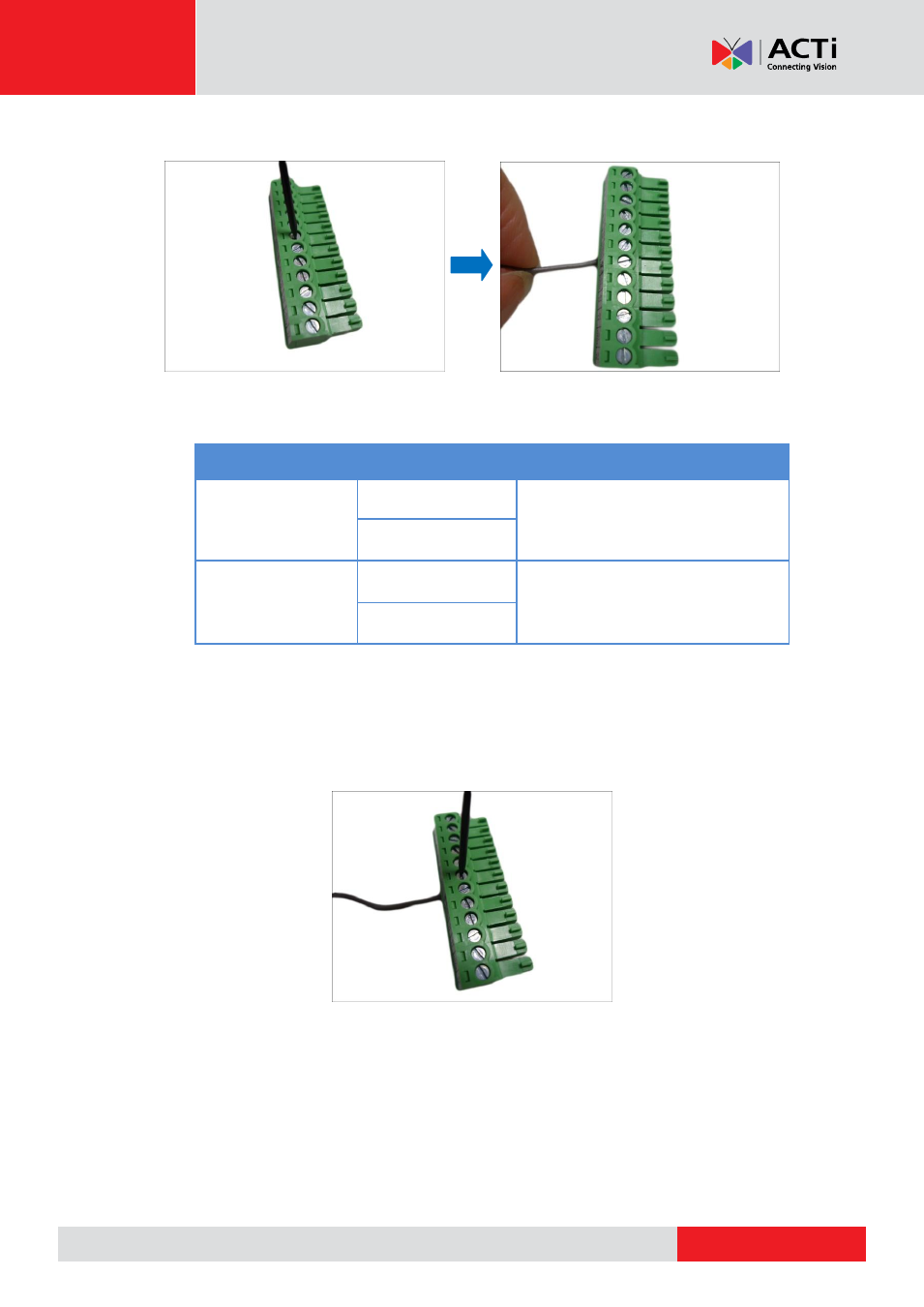
1.
Loosen the screw of the pin and insert the wire through the pin slot.
2.
To connect digital input / output devices (DI/DO), map the pins to one of the pin combinations
below:
Device
Pin Label
Mapping Instructions
Digital Output (DO)
DIO (port number)
Connect the wires of the output
device to a
DIO
and
DIO
12V
.
DIO 12V
Digital Input (DI)
DIO (port number)
Connect the wires of the input device
to
DI
and
DIO
GND
.
DIO GND
NOTE:
For every digital output device, a wire must also be mapped to the
12V
pin. Same
with for every digital input device, a wire must also be mapped to the
GND
pin. The
GND
and
12V
pins may be mapped with more than one device.
3.
Tighten the screws to secure the wires within the pin slot.
This manual is related to the following products: