Connecting the digital input/output, Devices (optional), Encoder hardware manual – ACTi V31 User Manual
Page 16
Encoder Hardware Manual
Connecting the Digital Input/Output Devices (Optional)
Depending on your surveillance needs, you may connect digital input / output devices to your
encoder.
Digital Input (DI) devices can be used to notify the encoder about an activity in the camera on the
encoder site
. DI can be triggers of events. For example, you can connect a “panic button” to the
encoder; as such when the panic button is pressed, the alarm signal will be sent through the
encoder. Other common DI device applications are emergency button, smoke detector, passive
infrared sensor, etc.
Digital Output (DO) devices are external devices that are activated by the encoder upon an event
within the encoder (e.g. video connection is lost, etc.) or triggered by motion in the camera site
among others
. For example, you can connect an “alarm horn” to the encoder; as such when an
event occurs on the camera side (e.g. detected intruder), the alarm horn will sound. Other
common DO device applications are motion-triggered lights, electric fence, magnetic door locks,
etc.
The digital input and output pins of V31 / V32 are configurable; meaning, either a digital input or
digital output device can be connected to a particular DIO pin. Once connected, the pin must be
defined through the Web Configurator (see the Encoder Firmware Manual for more information).
V31 has 8 DIO ports and V32 has 16 DIO ports.
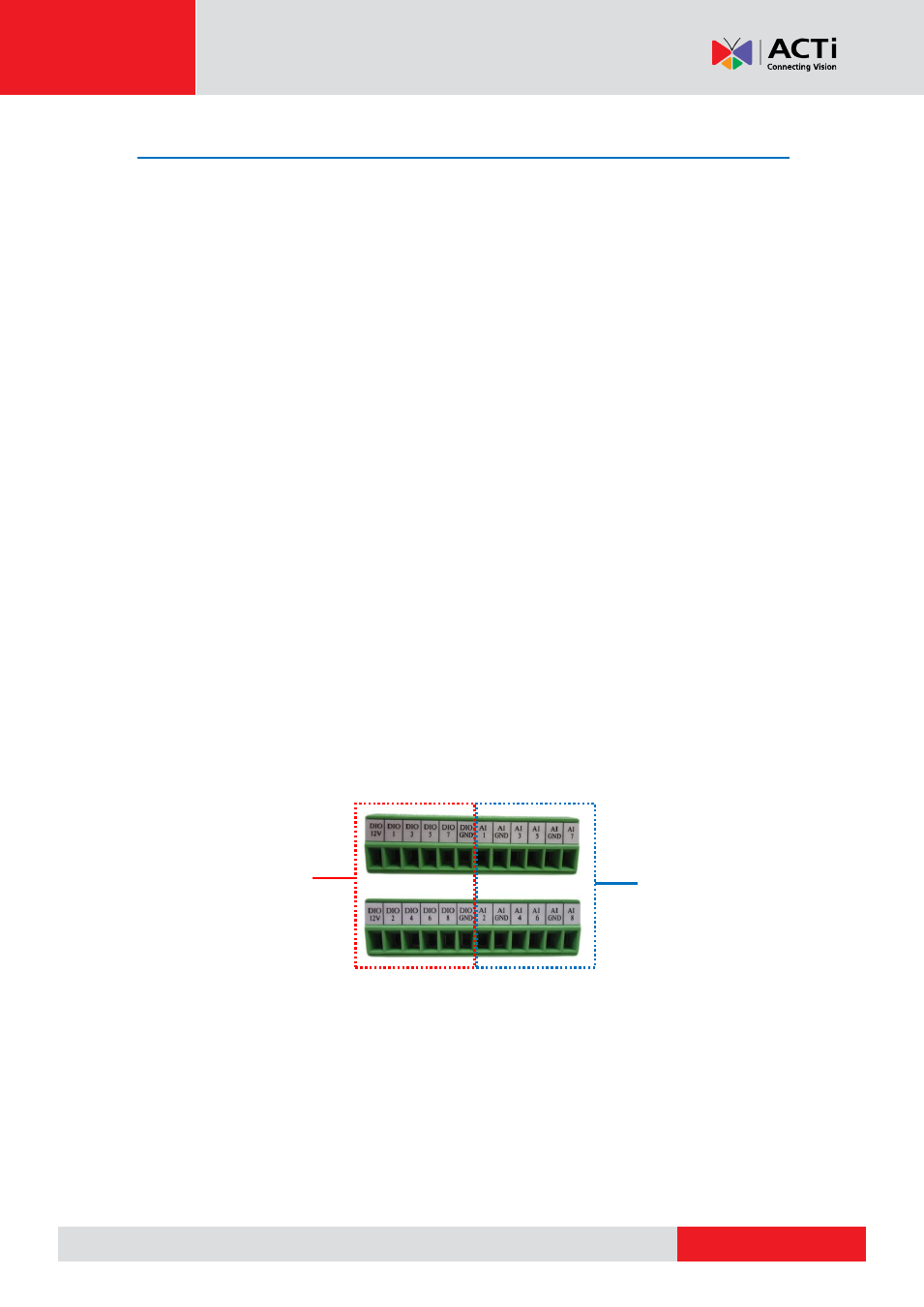
Four (4) DIO ports share the same terminal block with four (4) audio input ports. For example,
DIO port 1, 3, 5, and 7 are on the same terminal block with audio input ports1, 3, 5, and 7. See
samples below:
For DIO
For audio input (AI)