1 analogue signals and remote control – Watson-Marlow 323Du User Manual
Page 24
Watson-Marlow 323E, 323S, 323U and 323Du User Manual
24
U, Du
17.1 Analogue signals and
remote control
Pump starting and direction may be remotely controlled by switches, and speed by
analogue signals, connected to the 25-way D connector at the rear of the pump. The
analogue interface will accept either 0-10 VDC or 4-20 mA signals.
To select analogue operation press the MODE key until “ana” is showing in the dis-
play. The AUTO icon will show on the display.
Pump speed will increase with an increasing analogue signal. The pump will be
stopped at 0V or 4mA. This interface is pre-calibrated at the factory and may not be
altered. If the analogue signal is too high the pump will display an error message
“E21” (Over signal). See 19 Error messages.
The remote stop/start input works with both manual and analogue control
modes. The remote direction input works only with analogue control mode.
Never apply mains voltage to the 25-way D socket.
Apply the correct signals to the pins shown below. Limit
signals to the maximum values shown. Do not apply
voltage across other pins. Permanent damage, not
covered by warranty, may result.
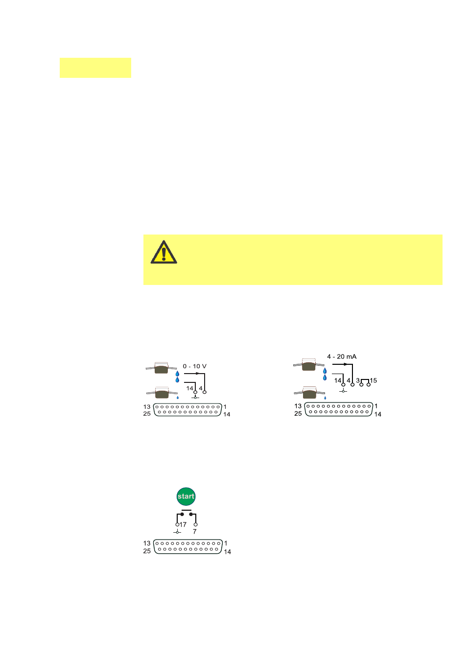
Analogue voltage signal pins 4 and 14
Input impedance 200 kohms
Maximum voltage signal 10V
Analogue current signal pins 4 and 14
link 3 and 15
Input impedance 250 ohms
Maximum current signal 20mA
Speed control
Stop/Start
A remote stop/start switch may be connected between pins 7 and 17 of the 25 pin
socket. Or a TTL compatible logic signal may be applied to pin 7. (Low 0V High 5V
maximum. Ground to pin 17). This is available in manual and analogue operation.