Front panel testing 3-2, Test switch 3-2 test access jacks 3-2, Net 3-2 mon 3-2 dte 3-2 – Verilink 2100 (34-00187) Product Manual User Manual
Page 18: Front panel testing
3-2
Operation
2100 CSU
9.
SET: This yellow LED flashes if the set code is trans-
mitted. It lights constantly if the set code is received.
10. RESET: This yellow LED flashes if the reset code is
transmitted. It lights constantly for five seconds if the
reset code is received.
11. ERR: This red LED lights 0.1 second if an error is
received during a network test.
12. Test Switch: This switch (FAR/LOC) is used for local
testing. Refer to
Test Switch below
for more information.
13. Test Access Jacks: These six bantam test jacks are
provided for access to the T1 line on the DTE side of
the CSU. Refer to
below for more
information.
Front Panel Testing
The previous section gave a brief description of each front
panel control and LED indicator. This section explains the
front panel test functions. Testing may also be performed
using software control from the TxPORT EM8000 element
manager (refer to the EM8000 reference manual).
Test Switch
This switch is used for local testing. When in the Far posi-
tion (FAR), the unit sends five seconds of IBLC (in-band
loop codes), then switches to Clear Test or BERT When
transmitting IBLC or the test pattern, the test LED blinks.
The ERR LED lights for 0.1 second when a bit error or sync
loss is detected.
When this switch is returned to the normal center position,
the unit sends five seconds of loop down code (100) and
then returns to its normal operating mode.
When the Test switch is in the local position (LOC), the unit
performs a bidirectional loopback as shown in the following
diagram and the LLB indicator lights.
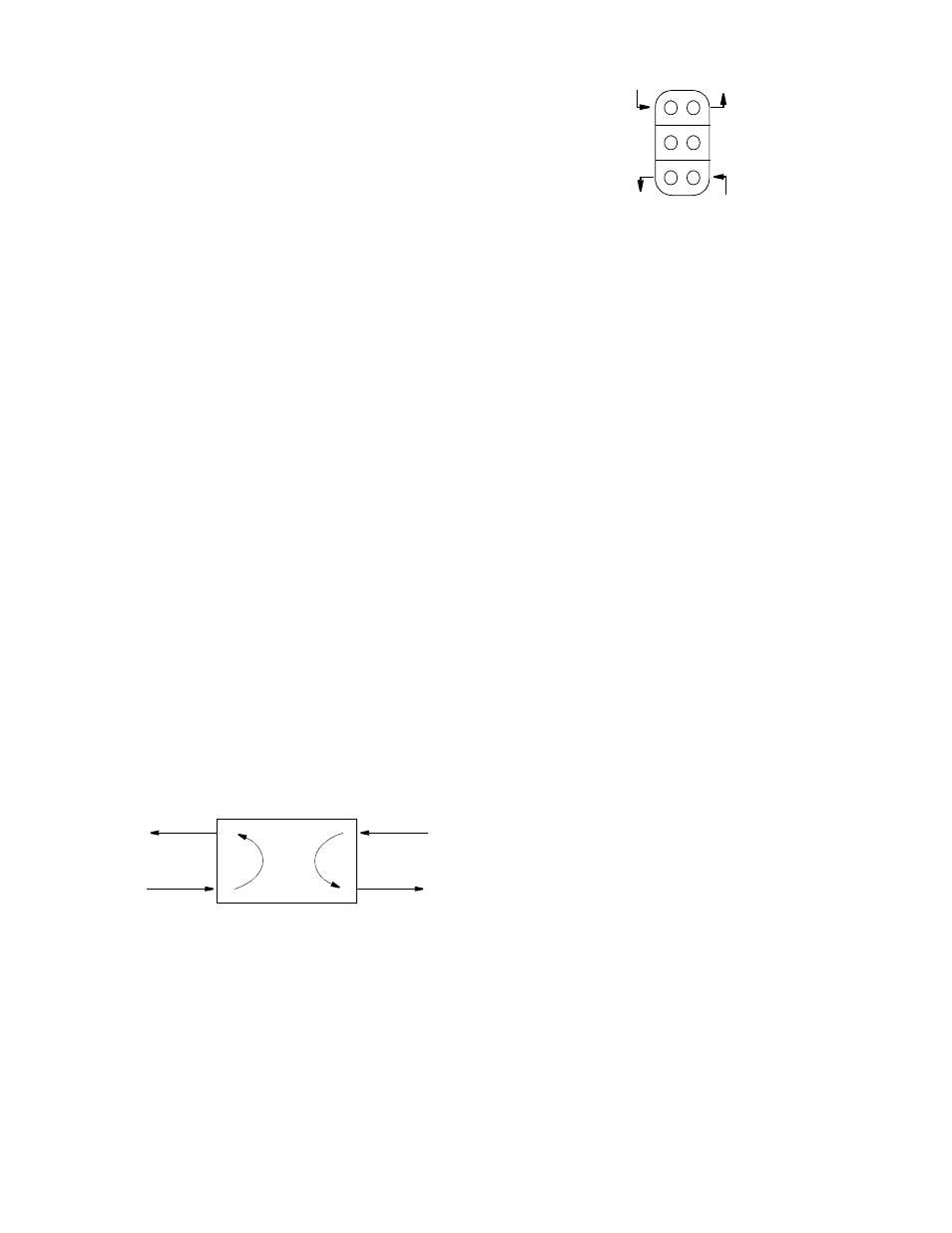
Test Access Jacks
Six bantam test jacks are provided for access to the T1 line
on the DTE side of the CSU. Jacks allow transmit and
receive toward the network, toward the DTE, or monitoring
traffic between DTE and network. Jacks are customarily
used to inject and receive T1 signals using a T1 test set.
NET
The top two ports are used to insert into the line in both
directions. They break connection to the DTE and make
connection to the CSU in the direction of the network.
MON
The middle two ports are used for non-intrusive bridge
monitoring of the line in both directions. They monitor the
signals passing through the CSU (between the DTE and the
network).
DTE
The bottom two ports are used to drop the line. They break
connection to the CSU and make connection to the DTE.
CSU
Equipment
Network
Figure 3-2
Local Loop
Receive signal
from the DTE
Transmit signal
to the network
Transmit signal
to the DTE
Receive signal
from the network
Monitor signal
from the network
Monitor signal
from the DTE
Figure 3-3
Test Jacks