Keep alive 2-3, Configuration switch s3 2-3, Aco/alarm card (optional) 2-3 – Verilink 2100 (34-00187) Product Manual User Manual
Page 11: Configuration switch s3, Aco/alarm card (optional)
Installation
2-3
2100 CSU
Keep Alive
Positions S2-6 and S2-7 are used to select the action that
occurs upon loss of DTE signal, when the unit switches to
the Keep Alive mode on the network line. The choices are
shown in Table 2-C.
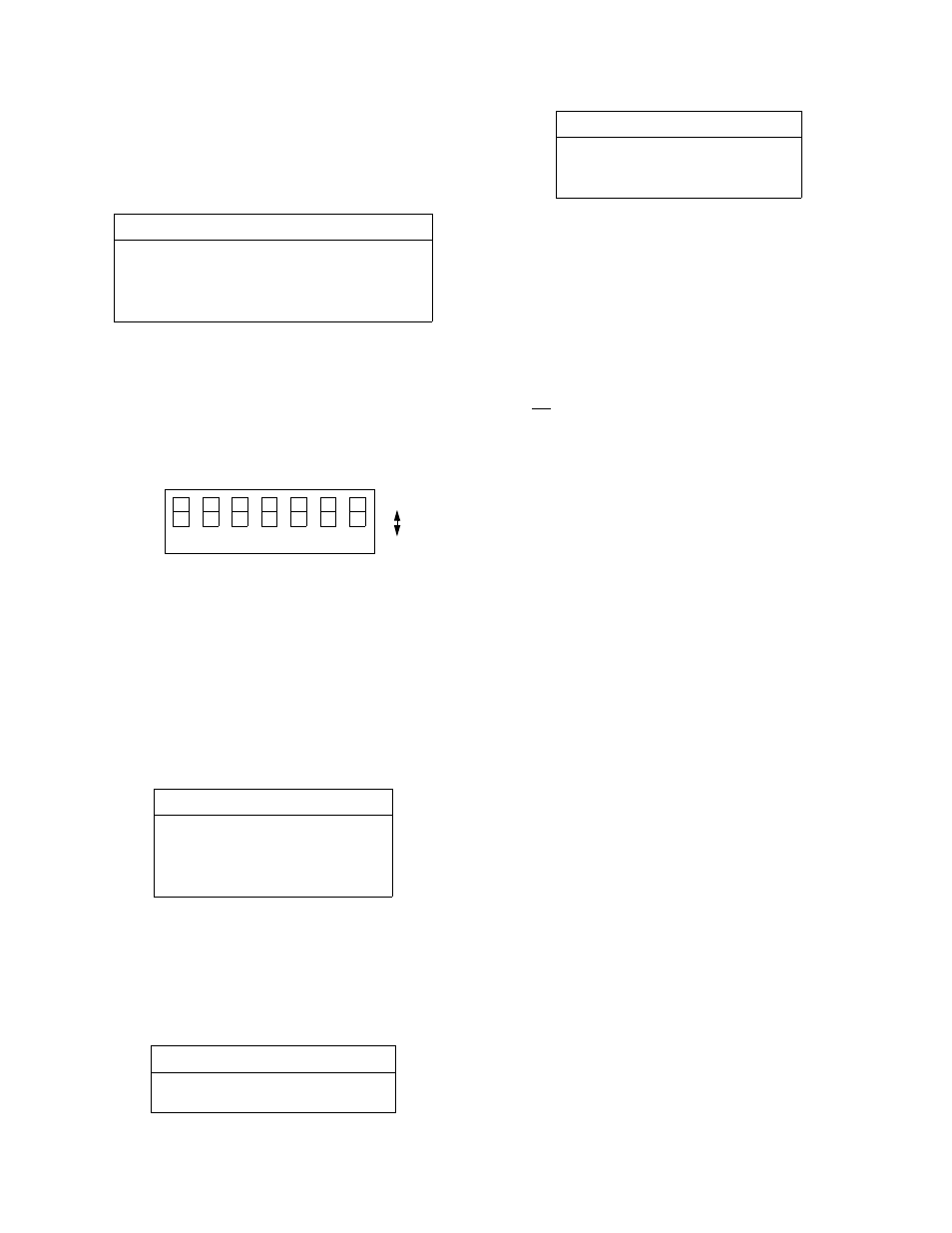
Configuration Switch S3
Switch S3 is used to set the configuration parameters listed
in the following paragraphs.
Network LBO
Positions S3-1 and S3-2 set the output signal level to the
transmit data (TXD) from the CSU to the network to the
proper line build out. These values are shown in Table 2-D.
The output level is factory set at 0 dB. It may be attenuated
by 7.5 dB, -15 dB, or -22.5 dB if operating conditions
require that it be changed. The telco should provide the
proper seting to the user. If unsure of the exact setting, then
leave it at 0 dB.
DSX Level
Positions S3-3, S3-4, and S3-5 set the DTE line interface
DSX level to one of the values shown in Table 2-E. The set-
ting should match the cable length from the CSU DTE port
to the attached equipment (cross-connect).
Line Code
Position S3-6 is used to provide AMI/B8ZS conversion from
the DTE to the facility and B8ZS/AMI conversion from the
facility to the DTE or set the line code to be transparent.
Up: Transparent
Down: Conversion
Remote Loop
Position S3-7 is used to select the signal sent to the DTE
during a remote loop.
Up: AIS to DTE
Down:Network data to DTE
ACO/Alarm Card (Optional)
The optional; ACO/alarm card monitors the alarm indica-
tors for an alarm active or an alarm clear condition and
provides closure contact points on the rear panel. The corre-
sponding front panel LED lights when an alarm condition is
detected on four different conditions:
• Network AIS (all ones)
• Network LOS (all zeros)
• Network BPVs
• DTE ones density)
The alarm card circuitry scans the status (on or off) of the
alarm indicators ten times a second (100-ms windows). The
card declares an alarm if one or more indicators are on for
100 consecutive 0.1-second samplings (10 seconds). When
this happens, the red Status indicator turns on until no alarm
conditions are detected for more than 100 consecutive 0.1-
second samplings (another 10 seconds).
Table 2-C
Keep Alive Settings
Function
S2-6
S2-7
Keep Alive is unframed all ones
Left
Left
Keep Alive is framed all ones
Left
Right
The Keep Alive signal is the acti-
vation of the line loopback.
Right
Left
Right
Right
Table 2-D
Network Line Build Out
Network LBO
S3-1
S3-2
0 dB
Down
Down
-7.5 dB
Down
Up
-15.0 dB
Up
Down
-22.5 dB
Up
Up
Table 2-E
DSX Level
DTE LBO
S3-3
S3-4
S3-5
0-133 ft
Up
Up
Down
134-266 ft
Down
Down
Up
1
2
7
6
5
4
3
NET LBO
NET LBO
DTE Le
v
el
DTE Le
v
el
DTE Le
v
el
Lin
e Co
de
Remo
te L
o
o
p
Figure 2-3
Switch S3
Up
Down
267-399 ft
Up
Down
Up
400-533 ft
Down
Up
Up
534-655 ft
Up
Up
Up
Table 2-E
DSX Level
DTE LBO
S3-3
S3-4
S3-5