Standalone unit 2-6 chassis unit 2-6, Network connection, Alarm connection (optional) – Verilink 2100 (34-00187) Product Manual User Manual
Page 14
2-6
Installation
2100 CSU
Network Connection
The network side of the CSU is referred to as the network
interface. This interface is located on the contains an ALBO
to allow the unit to be located a substantial distance away
from the telco network interface (receive signal level down
to -30 dB).
The network interface line build out (LBO) levels should be
adjusted as in Table 2-D on page 2-3. The maximum sug-
gested cable lengths for connection of the CSU to the
network are shown in Table 2-H. Calculations are based on a
70°F cable temperature; a 0.083 µF capacitance; a 30-dB
loss; and a 100-
Ω
, non-loaded, twisted pair cable. PIC refers
to Plastic Insulated Cable.
The network physical interface for both the standalone unit
and chassis unit is a standard RJ-48C 8-pin modular jack
with the pinout shown in Table 2-I.
In accordance with FCC rules, Part 68.218(b),
notify the telephone company before disconnect-
ing the CSU.
Alarm Connection (Optional)
The standalone unit and the chassis modular unit provide
rear panel alarm relay contacts as an option. These dry (iso-
lated) alarm contacts permit connection to a remote
indicating device.
The unit allows normally open (NO) or normally closed
(NC) alarm relay contacts. Using NO contacts, a nest of
CSUs and any other equipment may use a common bused
alarm line. Using a NC contact set allows a serial daisy
chain from unit to unit. Any unit going into alarm then
breaks the alarm loop.
Standalone Unit
The connection for the standalone unit is made on pins 5 and
6 of the Alarm/Power connector as shown in Table 2-J.
Pin 5 is configured to operate in either a normally open
(NO) or normally closed (NC) mode as determined by the
setting of the alarm relay jumper shown in Figure 2-7. This
jumper is located on the circuit board.
NO and NC refer to the contact’s relationship to the com-
mon contact under a no alarms condition. Move the jumper
to NC for normally closed operation (opens on alarm) or to
NO for normally open operation (closes on alarm).
Make connections to the alarm contacts using 20-gauge
stranded (or similar) wire. The contacts are rated at 120 mA
AC or 120 mA DC.
Chassis Unit
Alarm conditions from all modules in the chassis are bused
together in parallel and are presented on a single set of alarm
relay contacts which permit connection to a remote indicat-
ing device. When connected, pins 3 and 4 on terminal strip
TB1 operate in normally open mode. Refer to the 1051-2
Chassis Configuration Guide for further information.
All PRISM 3001 modules in a common chassis
must use the normally open contact mode.
Make connections to the alarm contacts using 20-gauge
stranded wire (or similar). The contacts are rated at 120 mA
AC or 120 mA DC.
Table 2-H
Line Loss versus Cable Gauge
Cable Type
Loss per 1000'
Max Length
26-gauge PIC
6.8 dB
4,400 ft
24-gauge PIC
5.4 dB
5,500 ft
22-gauge PIC
4.2 dB
7,100 ft
19-gauge PIC
3.0 dB
10,000 ft
Table 2-I
Network Interface Pinout
Pin
NET Interface
1
Data In
2
Data In
3
Not Used
4
Data Out
5
Data Out
6
Not Used
7, 8
Chassis Ground
Table 2-J
Power and Alarm Connector Pinout
Pin
Function
1
48 VDC Return
2
Signal Ground
3
-48 VDC
4
Frame Ground
5
Alarm Contact
6
Alarm Common
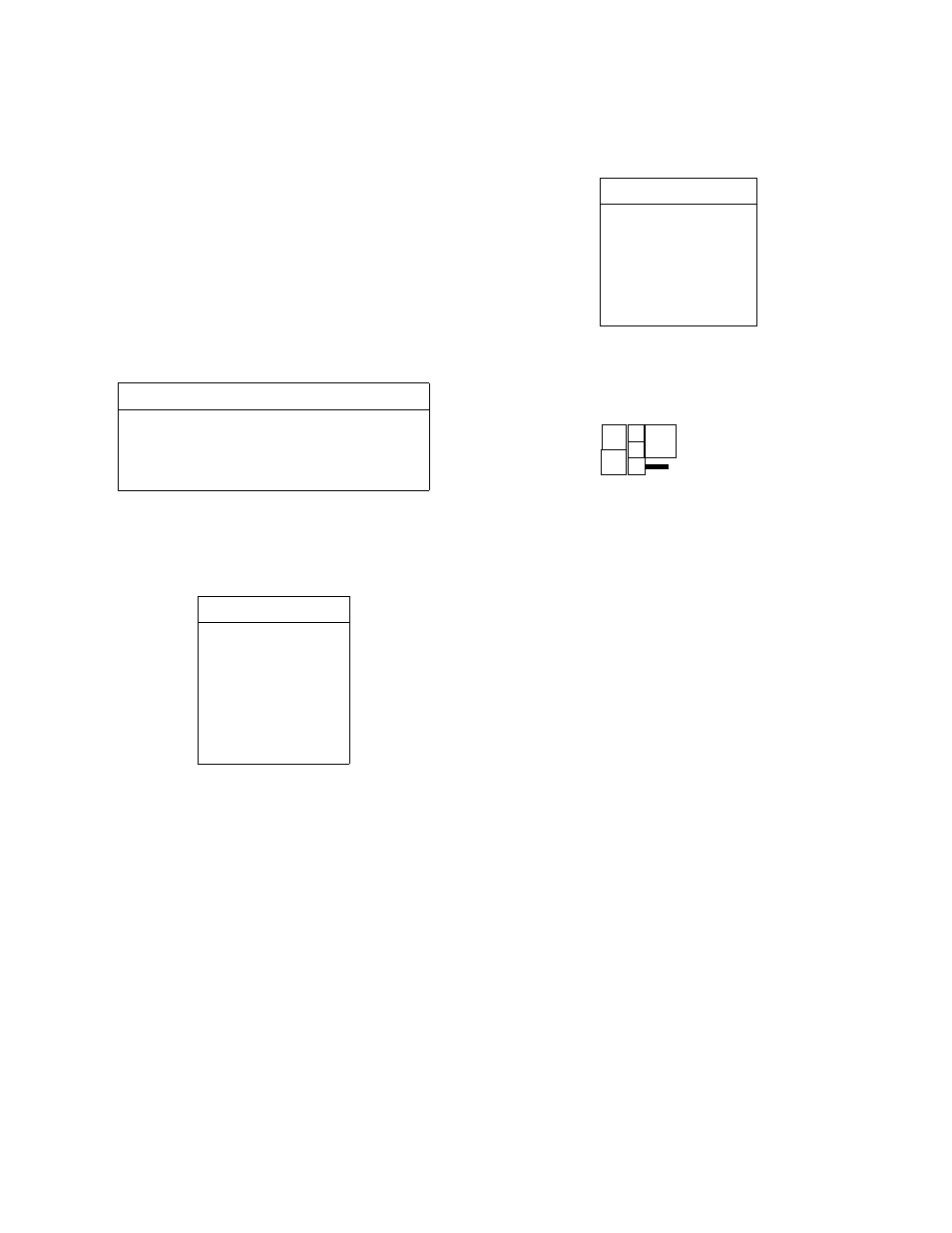
Figure 2-7
Alarm Relay Jumpers and Strap
NO
NC