2 front panel testing – Verilink 2048 (34-00179) Product Manual User Manual
Page 20
3-2
Operation
2048 PMU/NTU
7)
AIS: This red ‘alarm indication signal’ lights if the
selected AIS condition is detected from the network or
equipment. Refer to Section 2.5.6 on page 2-3.
8)
REM ALM: This LED lights constantly when a
remote (yellow) alarm signal is received.
9)
LOC ALM: This LED lights when a local alarm
exceeding alarm thresholds exists.
Refer to Section 4.6.2 on page 4-10 for more information
on alarm thresholds.
3.1.3
Test Controls and Indicators
10) LLB: This red LED lights to indicate that the unit is in
a line loopback condition.
11) PLB: This red LED lights to indicate that the unit is in
a payload loopback condition.
12) TST: This red LED lights constantly if the PMU has
been placed in a local or remote test loop. It blinks while a
loop or unloop code is being sent.
13) ERR: This red LED lights 1 second when BERT error
or sync loss is detected. It lights continuously to indicate
high bit error rates or loss of pattern sync. A loss of pattern
sync may be due to the far end not responding to the IBLC.
14) Test Switch: This switch (FAR/LOC) is used for local
testing. Refer to Section 3.2.1 for more information.
15) Test Access Jacks: These bantam jacks are provided
for access to the E1 line on the DTE side of the PMU. Refer
to Section 3.2.2.
16) Supervisory Port: The supervisory jack provides
direct terminal access to control the unit and gather status /
facility performance data. Refer to Section 3.2.3.
17) Pattern Select: This rotary switch determines the
BERT pattern sent by the unit when the test switch is in the
‘FAR’ or ‘LOC’ position. Refer to Section 3.2.4.
3.2
Front Panel Testing
The previous section gave a brief description of each front
panel control and LED indicator. This section explains the
front panel test functions. Testing may also be performed
using software control from the EM8000 element manager
or the Terminal Interface program.
3.2.1
Test Switch
This switch (labeled ‘Far/Loc’) is used for local testing.
When in the ‘Far’ position, the unit sends 5 seconds of
IBLC (inband loop codes), then switches to the test pattern
selected by rotary switch SW1 (Pattern Select). When trans-
mitting IBLC, the test LED blinks. When transmitting a test
pattern, it lights continuously. The ‘ERR’ LED lights for 1
second when a bit error or sync loss is detected.
When the test switch is returned to the ‘normal’ center posi-
tion, the unit sends 5 seconds of loop down code (
100
) and
then returns to its normal operating mode.
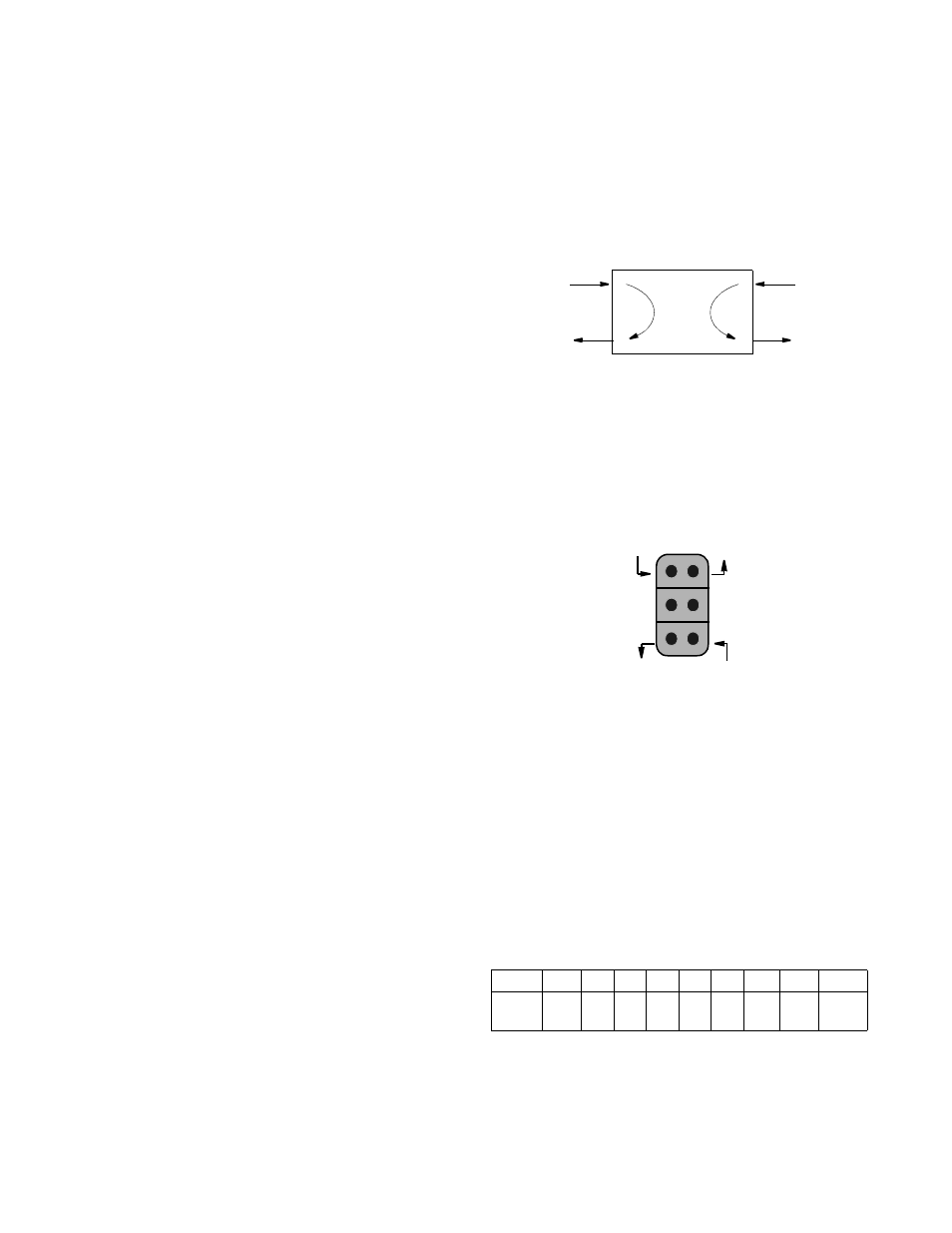
When the Test switch is in the ‘Local’ position, the unit per-
forms a bidirectional loop as shown below. The ‘LLB’ and
‘Test’ LEDs should be lit.
3.2.2
Test Access Jacks
Six bantam test jacks are provided for access to the E1 line
on the DTE side of the PMU. Two are used for non-intrusive
bridge monitoring of the line in both directions (MON). Two
are used to drop the line (DTE) and two are used to insert
into the line in both directions (NET). Jacks are customarily
used to inject and receive E1 signals using an E1 test set.
3.2.3
Supervisory Port
This 6-pin modular RS232 supervisory jack provides direct
terminal access for controlling the unit and gathering status
and performance data. A terminal may be connected to this
port for external software control. A modem may be con-
nected for remote access.
3.2.4
BERT Pattern Select
Rotary Switch SW1 determines the BERT pattern sent when
the Test switch is in the ‘Far’ position. The following table
shows the corresponding BERT test pattern sent when the
rotary switch is set to positions ‘0’ through ‘7’.
Firmware Upgrades: Field software upgrades are accom-
plished using position 9 and the ‘Supervisory’ port. Refer to
Section 2.5.1 on page 2 -2 for more information.
Pos
0
1
2
3
4
5
6
7
9
Pattern QRW
2
7
2
9
2
15
2
20
2
23
1:8 3:24 PROM
Dnload
PMU
Equipment
Network
Receive signal
from the DTE
Transmit signal
to the network
Transmit signal
to the DTE
Receive signal
from the network
Monitor signal
from the network
Monitor signal
from the DTE