Verilink 2048 (34-00179) Product Manual User Manual
Page 14
Installation
2-7
2048 PMU/NTU
This port is a serial RS232 DCE port configured for 8 bits,
no parity, and 1 stop bit.
2.8.3
User Port
The USER port (labeled ‘USER – IN/OUT’) is located on
the rear panel. The function of this port is identical to that of
the PTT port with the following exception. The USER port
does not allow the clearing of PTT data and the PTT port
does not allow clearing the USER data. This is explained
further in Section 4.4 on page 4-5. The physical connection
is a 6-pin modular connector with the following pinout
assignments.
2.8.4
Chassis Network Management
The operation of the EM8000 in the 12-slot chassis is simi-
lar to the stand-alone operation. Within the chassis, each
element is physically connected to the next element in a
daisy chain fashion. Signals from all modules are gathered
and presented on consolidated 6-pin modular connectors on
the rear panel, labeled ‘NMS IN’ and ‘NMS OUT’. The
front panel ‘SUPV’ port operates in the same fashion as in
the stand-alone unit.
When used in the chassis, the communications bus is auto-
matically tied into each unit, allowing single point interfac-
ing to the chassis. Cards may be inserted and removed from
Pin
PTT In
PTT Out
1
Not Used
Not Used
2
Signal Ground
Signal Ground
3
Data Out
Data Out
4
Data
In Not
Used
5
Signal Ground
Signal Ground
6
Not Used
Not Used
Pin
USER In
USER Out
1
Not Used
Not Used
2
Signal Ground
Signal Ground
3
Data Out
Data Out
4
Data In
Not Used
5
Signal Ground
Signal Ground
6
Not Used
Not Used
J1
2
J1
3
J1
4
J1
5
J1
6
J4
J5
J6
J7
J8
J1
2
J1
3
J1
4
J1
5
J1
6
J4
J5
J6
J7
J8
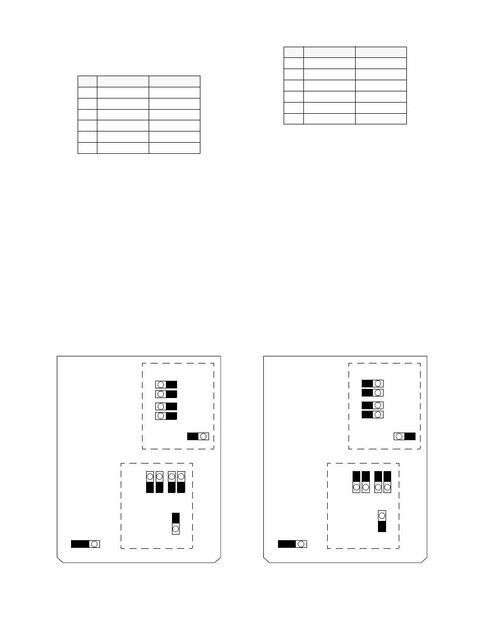
Figure 2-4
75 ¾ Jumper Configuration
Front
Network
Equipment
Front
Network
Equipment
NO
NC
J18
NO
NC
J18
Rear
Rear