Ordering numbers, Supplied materials, Unit configuration – Verilink 300 (34-00199) Product Manual User Manual
Page 8: Nstallation
8
9
Ordering Numbers
Both the TxPORT 300 and 310 units are shipped from the factory with the 300/310
DSU /CSU reference manual. The user may require additional items for the installation
and operation of each unit. Use the following numbers to order the basic unit or
optional equipment.
2. I
NSTALLATION
This chapter contains information and instructions required to prepare the TxPORT
300 and 310 DSU /CSUs for use. Included are configuration guidelines and connection
instructions.
The only difference between the two units is that the 300 has two ESF operation
modes. Therefore, the DIP switch position that controls this mode is not functional on
the 310 unit.
Throughout this manual, all factory default settings are shown underlined (the
‘A’ position is the default setting for all switches).
Part Number
Description
F -300 - 001 - - 111
300 ESF CSU productivity series unit
F -310 - 001 - - 111
310 CSU productivity series unit
9 - 2000 -001 -1
Single unit horizontal rack mount hardware for 19-inch equipment rack
9 - 2000 -001 -2
Dual unit horizontal rack mount hardware for 19-inch equipment rack
9 - 2000 -002 -1
Single unit horizontal rack mount hardware for 23-inch equipment rack
9 - 2000 -002 -2
Single unit horizontal rack mount hardware for 23-inch equipment rack
✍
Supplied Materials
The TxPORT 300 Productivity Series units are shipped from the factory with the 300/
310 DSU/CSU reference manual. The user may require additional items for unit
installation and operation. Refer to page 8 for complete ordering information.
Unit Configuration
The following sections describe the configuration of the 300 and 310 models. These
units were designed to be operated from manual DIP switch control. Refer to the dia-
grams in this chapter for switch locations.
On power up, each unit is configured to the hardware settings of the option switches.
Subsequent changes to these settings will not take effect until the unit has been reset.
This may be accomplished either by removing and then reapplying power or by push-
ing the test switch toward local loop ‘LL’ and then quickly back to ‘NORM’. The unit
will then recycle through its LEDs and read the new configuration.
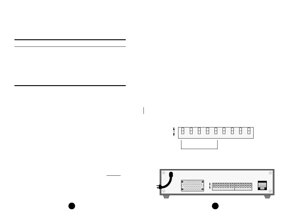
Configuration Switch S1
Switch S1 is a 9-position DIP switch located on the CSU rear panel. This switch pro-
vides the following configuration parameters:
A
B
6
5
4
3
1
7
9
8
2
56 kbps
Contiguo
us
Contro
l
Data I
nver
t
64
kbp
s
Alt
er
n
ate
Contr
o
l
D
ata
In
v
ert
Fo
ll
ow
On
No
Ye
s
DSOs Assigned
(see table)
Switch
S1
8
1
NET
TxPORT Models 300 and 310 Rear Panel
7
6
5
4
3
2
1
8
6
5
4
3
2
1
7
S1
S2
A
B
V.35
93 - 130
VAC
9