Productivity series 300, Able of, Ontents – Verilink 300 (34-00199) Product Manual User Manual
Page 3: General, Installation, Operation, Customer service
SD
RD
FRAME
ERROR
YELLOW
TEST
NORM
RL
LL
PRODUCTIVITY
SERIES
300
CSU/DSU
T
R
A
N
S
P
O
R
T
®
T
ABLE OF
C
ONTENTS
1. General
..................................................................4
Specifications ................................................................................ 5
FCC Requirements ........................................................................ 6
Warranty ....................................................................................... 7
Ordering Numbers ........................................................................ 8
2. Installation ..............................................................8
Supplied Materials ........................................................................ 9
Unit Configuration ........................................................................ 9
Configuration Switch S1 ....................................................... 9
Configuration Switch S2 ....................................................... 11
Connections .................................................................................. 12
V.35 Port Connection ............................................................ 12
Network Connection .............................................................. 13
3. Operation ..............................................................13
Testing .......................................................................................... 13
4. Customer Service ...................................................16
Telephone....................................................................................... 16
E-mail............................................................................................. 16
World Wide Web ........................................................................... 16
3
14
Remote Channel Loop: Each unit can generate a far end remote channel loop by
placing the test switch in the ‘RL’ position. The unit sends a V.35 loop code in the as-
signed channels to the far end for two seconds followed by two seconds of all ones, fol-
lowed by DTE data. After four seconds, the far end should be looped.
In other words, this function starts an internal test by replacing the DSUs transmitted
data with the V.54 activate code to the far end DSU equipment for the proper time peri-
od. Then a test pattern is sent to verify the looped channel’s integrity. If the transmitted
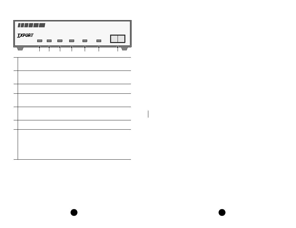
Productivity 300/310 DSU/CSU (model 300 shown)
1 Send Data: This green LED lights when the SD data lead is a mark and is off
when the lead is a space. Therefore, the LED will vary from full intensity to off
depending on the relative number of marks and spaces.
2 Receive Data: This green LED lights when the RD data lead is a mark and is off
when the lead is a space. Therefore, the LED will vary from full intensity to off
depending on the relative number of marks and spaces.
3 Frame: This green LED lights when the unit is in frame synchronization with the
T1 line.
4 Error: This red LED lights if the internal alarm circuitry detects any of the fol-
lowing conditions from the incoming T1 signal: BPVs, FBEs, CRCs, loss of
signal/loss of sync, or more than 175 zeros.
5 Yellow: This red LED lights if the internal alarm circuitry detects a remote (yel-
low) alarm signal from the far end terminal equipment. This occurs if the far end
terminal is out of sync with the T1 signal from the network.
6 Test: This amber LED remains lit if the unit is in a test mode, either by manually
depressing the loop switch or by receipt of a test command from the facility.
7 Test Switch: This 3-position switch is used as follows: Depressing the switch to
the ‘LL’ position places the unit in a local loop mode. Data from the DTE is looped
back to the DTE and is also transmitted to the network (the data from the network
is open). Depressing the switch to the ‘RL’ position initiates an automated V.54
remote loop and BERT sequence of assigned data channels. The ‘TEST’ LED will
be green if the test is successful (the far end unit loops and returns the data error
free with the V.54 code). If errors are detected, the ‘TEST’ LED will be red.
7
5
4
3
2
1
6