Eneral, Testing, Peration – Verilink 300 (34-00199) Product Manual User Manual
Page 4: Productivity series 300
13
4
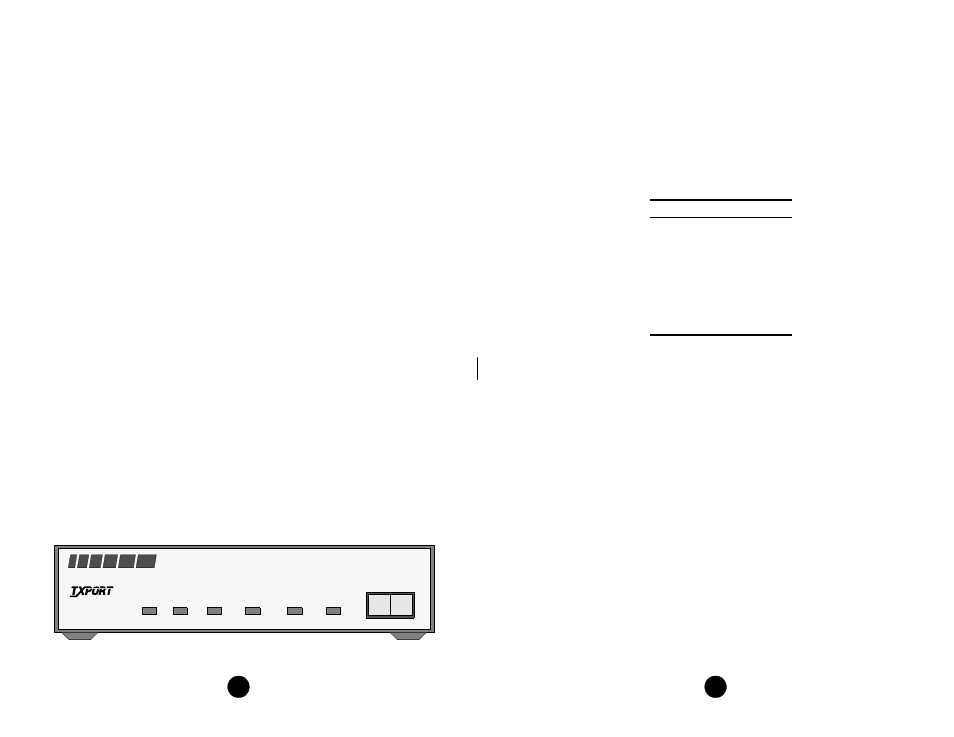
Productivity 300/310 DSU /CSU (model 300 shown)
The connector is a standard 34-pin female V.35. Only circuits serviced by the unit are
listed. When two pins are listed, the first is the “A” differential pin and the second is
the “B” differential pin.
All balanced bipolar inputs and outputs meet the physical and electrical specifications
at ITU V.35. All unbalanced bipolar inputs and outputs meet the physical and electrical
specifications of ITU V.28.
Network Connection
The network T1 facility interface is a standard RJ-48C 8-pin modular jack with the
following pinout:
3. O
PERATION
This chapter describes the front panel operation and test features of the TxPORT 300
and 310 CSUs. Both units are controlled manually using a front panel test switch and
rear panel DIP switches (the DIP switches are discussed in the ‘Installation’ chapter).
The controls, indicators and test features are identical for both units except for refer-
ences to T1.403 or 54016 loops, which are specific to the 300 unit only.
Testing
The front panel test switch is used as described in the following paragraphs. Four types
of loops are shown on page 15.
Local Loop: Each unit can initiate a local loop by placing the test switch in the ‘LOC’
position. The unit loops the signal from the customer equipment (DTE IN) back to the
customer equipment (DTE OUT). It also transmits the DTE data towards the network.
Pin
Assignment
1
Data In
2
Data In
3
Not Used
4
Data Out
5
Data Out
6
Not Used
7/8
Chassis Ground
1. G
ENERAL
The TxPORT Productivity Series CSU/DSU models 300 and 310 provide an eco-
nomical solution for interfacing customer high speed digital applications to industry
standard T1 or fractional T1 facilities. These units are designed for standalone
(tabletop) use, but they may be rack mounted (refer to the Ordering Numbers section
on page 8).
The main difference between the model 300 and the 310 is in the function of a DIP
switch which controls the ESF operating mode on the 300, but has no function on
the 310 unit. Any resulting differences will be noted in the appropriate places
throughout this manual.
The 300 unit is fully compatible with both ANSI T1.403 and AT&T 54016 ESF
performance monitoring, testing, and reporting requirements. Both units support
D4/ESF framing and AMI/B8ZS line encoding.
LED indicators are provided on the front panel of each unit to alert local personnel
of alarm conditions, loop/test status, and DTE port activity. A test switch allows
local and remote loops to be activated. The 300 unit also supports FDL loopbacks.
The 300 and the 310 rear panels have two interface connectors - an RJ-48C network
interface connector and a V.35 high speed port connector. The V.35 port supports
data rates up to 1.536 Mbps (in increments of either 56 kbps or 64 kbps).
A power cord on each unit provides 115 VAC operation. Primary and secondary
surge protection is provided on the network side (meeting UL 1459 requirements).
Each unit provides network automatic line build out (ALBO) circuitry. This network
ALBO supports a receive range of +1 dB down to -27 dB. These units also provide
network line build out (LBO) circuitry. The transmit LBO is user selectable from 0
dB down to -22.5 dB.
SD
RD
FRAME
ERROR
YELLOW
TEST
NORM
RL
LL
PRODUCTIVITY
SERIES
300
CSU/ DSU
T
R
A
N
S
P
O
R
T
®