Fcc requirements – Verilink 300 (34-00199) Product Manual User Manual
Page 6
6
11
FCC Requirements
Changes or modifications to this unit not expressly approved by the
party responsible for compliance could void the user’s authority to oper-
ate the equipment.
This device complies with Part 15 of the FCC rules. Operation is subject to the fol-
lowing two conditions:
1)
This device may not cause harmful interference.
2)
This device must accept any interference received, including interference that
may cause undesired operation.
This equipment has been tested and found to comply with the limits for a Class A
digital device, pursuant to Part 15 of FCC Rules. These limits are designed to pro-
vide reasonable protection against harmful interference when the equipment is oper-
ated in a commercial environment. This equipment generates, uses, and can radiate
radio frequency energy and if not installed and used in accordance with the instruc-
tion manual, may cause harmful interference to radio communications. Operation of
this equipment in a residential area is likely to cause harmful interference. The user
will be required to correct the interference at his own expense.
Notice to Users of 1.544 Mbps Service: The following instructions are provided to
ensure compliance with FCC Rules, Part 68:
1)
All direct connections to T1 lines must be made using standard plugs and jacks.
2)
Before connecting your unit, you must inform the local telephone company of
the following information:
3)
If the unit appears to be malfunctioning, it should be disconnected from the
telephone lines until you learn whether the source of trouble is your equipment or
the telephone line. If your equipment needs repair, it should not be reconnected until
it is repaired.
4)
The unit has been designed to prevent harm to the T1 network. If the telephone
company finds that the equipment is exceeding tolerable parameters, they can tem-
porarily disconnect service. In this case, the telephone company will give you
advance notice, if possible.
5)
Under FCC rules, no customer is authorized to repair this equipment. This
restriction applies regardless of whether the equipment is in or out of warranty.
Port ID REN
/
SOC FIC
USOC
12 - 00492
6.0 N
04DU9- BN
04DU9- DN
04DU9-1ZN
04DU9-1KN
04DU9-1SN
RJ-48C jack
quirements are maintained by the idle channels rather that placing any restrictions on
the high speed data.
A - Contiguous
B - Alternating
Control Lines: Position S1- 8 selects the control line operation. Control lines support-
ed are RTS, CTS, DSR, CD, LL, and TM. With ‘On’ selected, the CTS, DSR, and CD
leads are permanently set to ON. With ‘Follow’ selected, the DSR lead follows T1
sync, the CTS lead follows RTS, and the CD lead follows the density status of the in-
coming T1 signal (
≥
175 zeros = CD OFF). The TM line goes high when the unit is in a
local or remote test mode.
A - On
B - Follow
Data Invert: Position S1-9 determines whether the data bits are inverted. The ‘Yes’
mode is useful in maintaining ones density control in certain data applications, such as
HDLC and X.25.
A - No
B - Yes
Configuration Switch S2
Switch S2 is a 7-position DIP switch located on the CSU rear panel. This switch pro-
vides the following configuration parameters:
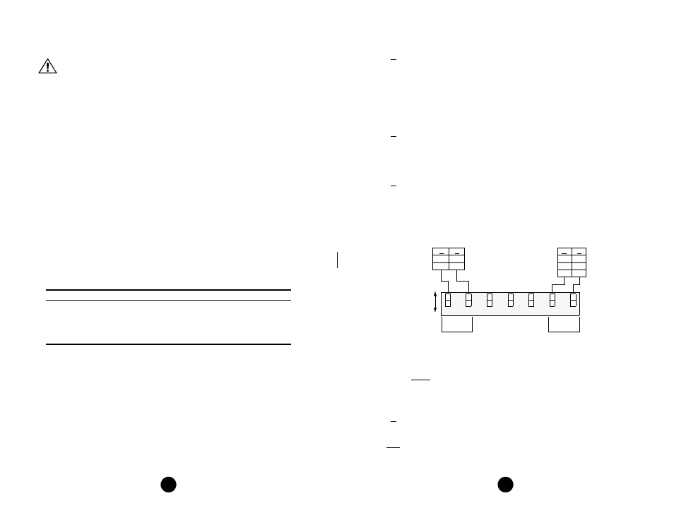
Timing Source: Positions S2-1 and S2-2 determine the source of unit clocking as
shown in the above diagram.
Operating Mode (Model 300 only): Position S2-3 sets the operating mode of the 300
unit. In the 54016 mode, the unit responds only to 54016 CSU messages. In the T1.403
mode, the unit responds to ANSI loop/unloop commands and generates a PRM every
second, but will not respond to 54016 messages. The two modes are exclusive of each
other.
A - 54016
B - T1.403
Network Framing: Position S2-4 sets the unit to the line framing of the network. In
the ESF mode, the units can be configured for either the T1.403 or 54016 mode. In the
54016 mode, the 300 unit responds to all 54016 messages. In the T1.403 mode, the 300
5
4
0
1
6
E
S
F
A
M
I
T
1
.4
0
3
D
4
B
8
Z
S
5
4
3
2
1
6
7
B
A
A
A
B
A
Network clock (looped)
Internal clock (master)
CPE clock (external)
Timing
Source
Network
LBO
B
B
B
A
A
A
B
A
0
-22.5
-7.5
-15
A
B