0 introduction, 4 orderingnumbers, Nstallation – Verilink 210 (34-00196) Product Manual User Manual
Page 8: 4 ordering numbers
8
9
standard for electronic equipment. TxPORT will pay shipping charges for delivery on
return. The customer is responsible for mode and cost of shipment to TxPORT. This
warranty does not apply if the unit has been damaged by accident, misuse or as a result
of service or modification by other than TxPORT personnel.
When returning the unit for warranty work, a Return Material Authorization (RMA)
number must be obtained from customer service (refer to
the last page of this manual
for phone numbers). When calling TxPORT to obtain a Return Material Authorization
number or to arrange service, please have the following information available:
•
Model number(s) and serial number(s) for the unit(s).
•
Reason for return and symptoms of problem.
•
Warranty status (if known).
•
Purchase order number to cover charges for out-of-warranty items.
•
Name and phone number of person we can contact if we have questions about the
unit(s).
•
Mode of shipment required (second day air is the normal mode of shipment for all
returned material unless otherwise specified).
As soon as TxPORT has the above information, the RMA that must accompa-
ny the item(s) returned can be issued.
1.4
Ordering Numbers
Both the TxPORT 200 and 210 units are shipped from the factory with the 200/ 210
CSU reference manual. The user may require additional items for the installation and
operation of each unit. Use the following numbers to order the basic unit or optional
equipment.
Part Number
Description
F -200 - 001 - - 111
200 ESF CSU unit
F -210 - 001 - - 111
210 CSU unit
30 - 00087
200 mA, wall mount power transformer, 115 VAC to -48 VDC
9 - 2000- 001 -1
Single unit horizontal rack mount hardware for 19" equipment rack
9 - 2000- 001 -2
Dual unit horizontal rack mount hardware for 19" equipment rack
9 - 2000- 002 -1
Single unit horizontal rack mount hardware for 23" equipment rack
9 - 2000- 002 -2
Single unit horizontal rack mount hardware for 23" equipment rack
I
NSTALLATION
2.0
Introduction
This chapter contains information and instructions required to prepare the TxPORT
200 and 210 CSUs for use. Included are initial inspection procedures, configuration
guidelines, connection instructions, and powering information.
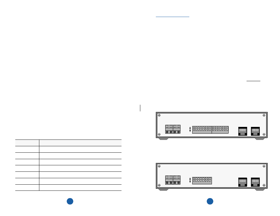
The differences between the 200 and 210 CSU units (which are covered in this chapter)
are summarized below:
•
DIP Switch S2 is found only on the 200 CSU.
•
Position S1-7 (switch S1, position 7) is a spare on the 200 CSU. On the 210 CSU,
position S1-7 is used to enable the ‘Transparent’ mode.
NOTE: Throughout this manual, all factory default settings are shown underlined
(the ‘A’ position is the default setting for all switches).
8
1
NET
TxPORT Model 200 Rear Panel
8
1
DTE
7
6
5
4
3
2
1
8
6
5
4
3
2
1
7
S1
S2
A
B
PWR
(+) GND
PWR
(-) GND
-20 to -56 VDC
MAX CURRENT, 100 MA
8
1
NET
TxPORT Model 210 Rear Panel
8
1
DTE
8
6
5
4
3
2
1
7
S1
A
B
PWR
(+) GND
PWR
(-) GND
-20 to -56 VDC
MAX CURRENT, 100 MA