1 suppliedmaterials, 2 unitconfiguration, 1 configurationswitchs1 – Verilink 210 (34-00196) Product Manual User Manual
Page 7: 3 warranty, 1 supplied materials, 2 unit configuration
10
7
Notice to Users of 1.544 Mb/s Service: The following instructions are provided to
ensure compliance with FCC Rules, Part 68:
1)
All direct connections to T1 lines must be made using standard plugs and jacks.
2)
Before connecting your unit, you must inform the local telephone company of the
following information:
Port ID: P/N/12 - 00492
REN /SOC (Service Order Code): 6.0 N
FIC (Facility Interface Code):
04DU9-BN
04DU9-DN 04DU9-1ZN
04DU9-1KN
04DU9-1SN
USOC jack:
RJ48C
3)
If the unit appears to be malfunctioning, it should be disconnected from the tele-
phone lines until you learn whether the source of trouble is your equipment or the tele-
phone line. If your equipment needs repair, it should not be reconnected until it is
repaired.
4)
The unit has been designed to prevent harm to the T1 network. If the telephone
company finds that the equipment is exceeding tolerable parameters, they can tempo-
rarily disconnect service. In this case, the telephone company will give you advance
notice, if possible.
5)
Under FCC rules, no customer is authorized to repair this equipment. This restric-
tion applies regardless of whether the equipment is in or out of warranty.
6)
If the telephone company alters their equipment in a manner that will affect the
use of this device, they must give you advance warning so that you can have the oppor-
tunity for uninterrupted service. You will be advised of your right to file a complaint
with the FCC.
7)
The attached affidavit must be completed by the installer.
8)
In the event of equipment malfunction, all repairs should be performed by our
company or an authorized agent. It is the responsibility of users requiring service to
report the need for service to our company or to one of our authorized agents.
1.3
Warranty
TxPORT warrants each unit against defects in material and workmanship for a period
of five years from the date the unit was shipped to the customer. If the unit malfunc-
tions at any time during the warranty period, TxPORT will repair, or at TxPORT’s
option, replace the unit free of charge.
The remedies listed herein are the users sole and exclusive remedies. TxPORT shall not
be liable for any indirect, direct, incidental or consequential damages. The owner must
return the unit to the factory, shipping prepaid and packaged to the best commercial
2.1
Supplied Materials
The TxPORT 200 and 210 CSUs are shipped from the factory with the 200/210 CSU
reference manual. The user may require additional items for the installation and opera-
tion of the units. Refer to
for complete ordering information.
2.2
Unit Configuration
The following sections describe the configuration of the 200/ 210 CSU. These units
were designed to be operated from manual DIP switch control. Refer to the diagrams
in
this chapter
for switch locations. The 210 unit is transparent to framed (D4 or ESF) or
unframed T1 signals. It is also transparent to line coding and may operate with either
AMI or B8ZS.
On power up, each unit is configured to the hardware settings of the option switches.
Subsequent changes to these settings will not take effect until the unit has been reset.
This may be accomplished either by removing and then reapplying power or by push-
ing the test switch toward ‘LOOP’ and then quickly back to ‘NORM’. The unit will
then recycle through its LEDs and read the new configuration.
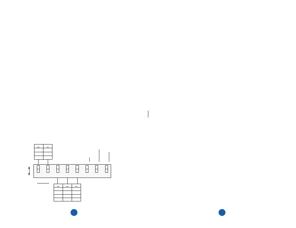
2.2.1
Configuration Switch S1
Switch S1 is located on the CSU rear panel. This switch provides the following config-
uration parameters:
A
L
oop
5
4
3
2
1
6
8
B
L
oop
AI
S
Networ
k
Data
7
Ones
Dens
ity
15
Z
eros
Ones
Dens
ity
175
Z
eros
D
TE A
M
I
to
N
E
T B
8
ZS
L
ine Code
T
ranspar
ent
B
B
B
A
A
A
B
A
0
-22.5
-7.5
-15
Network
LBO
B
A
A
B
A
B
A
B
A
A
B
A
B
B
B
DTE LBO
134 - 266 FT.
0 - 133 FT.
267 - 399 FT.
400 - 533 FT.
534 - 655 FT.
(dB)
Configuration Switch S1
Note: position 7
is used only on
the 210 CSU