3 connections, 1 dteandnetworkconnections, 2 powerconnection – Verilink 210 (34-00196) Product Manual User Manual
Page 4: 0 introduction, Eneral
13
4
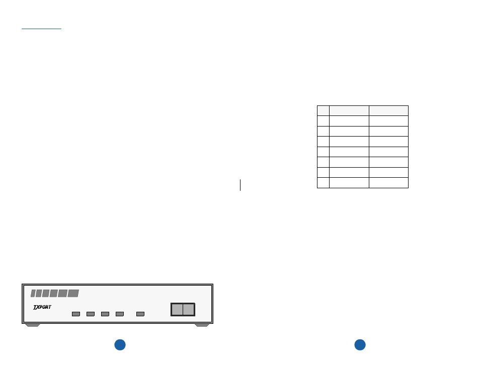
TxPORT 200 CSU
2.3
Connections
Both 200 and 210 CSU rear panels have RJ48C connections for the network and DTE
interface and a terminal strip for the power connection. The following paragraphs de-
scribe these connections.
2.3.1
DTE and Network Connections
The equipment and network physical interfaces are standard RJ48C 8-pin modular
jacks with the following pinout.
2.3.2
Power Connection
The 200 and 210 CSU units operate from -48 Volts DC. Connections are made on the
following power terminals using 20-gauge stranded (or similar) wire:
GND Ground
PWR-
-48 VDC (± 6 V, 45 mA)
PWR+ Return
Pin NET Interface DTE Interface
1
Data In
Data Out
2
Data In
Data Out
3
Not Used
Not Used
4
Data Out
Data In
5
Data Out
Data In
6
Not Used
Not Used
7/8 Chassis Ground Chassis Ground
G
ENERAL
1.0
Introduction
The TxPORT Productivity Series 200 ESF CSU and 210 CSU provide an economical
solution for providing the T1 interface between customer premise equipment and T1
facilities (telco or private). Each unit is compatible with all T1 carrier transmission
equipment and is designed to comply with all industry standard specifications. Both the
transmitted and received 1.544 Mbps signals are conditioned.
The 200 unit is an industry standard, ESF T1 channel service unit which supports ESF
performance monitoring, testing, and performance reporting per AT&T 54016 and
ANSI T1.403.
The 210 unit is an industry standard, frame transparent T1 channel service unit. It
detects and activates network initiated loopbacks, monitors bipolar violations, and
maintains pulse density of the transmitted signal. The unit works with any T1 line for-
mat and is transparent to framed (D4 or ESF) or unframed T1 signals. The 210 unit is
transparent to line coding and may operate with either AMI or B8ZS.
Both units are constructed for stand-alone (tabletop) use but may be installed in an
equipment rack or cabinet (requiring optional rack mount hardware). The front and rear
panels of the two units are similar. Any differences will be noted in the appropriate
places throughout this manual.
Each unit provides ALBO circuitry on the network receive path. The network ALBO
supports a receive range of +1 dB to -30 dB. The DTE supports DSX1 signal ranges up
to 655 feet. The units also provide LBO circuitry on both network and DTE. The net-
work transmit LBO is user selectable (from 0 dB to -22.5 dB). The DTE transmit LBO
is user selectable in five incremental ranges from 0 to 655 feet.
Both CSU units operate from an externally provided -24 or -48 VDC power source.
Network and DTE connections are made through RJ48C type connectors. The units
have primary and secondary surge protection on both the network and DTE side (meet-
ing the UL 1459 requirements).
LOOP
NORM
CSU
PWR
DTE
NET
LOOP
FAR
PRODUCTIVITY
SERIES
200
T
R
A
N
S
P
O
R
T
®