Verilink 2010 (34-00204) Product Manual User Manual
Page 9
2-2
Installation
2010 CSU
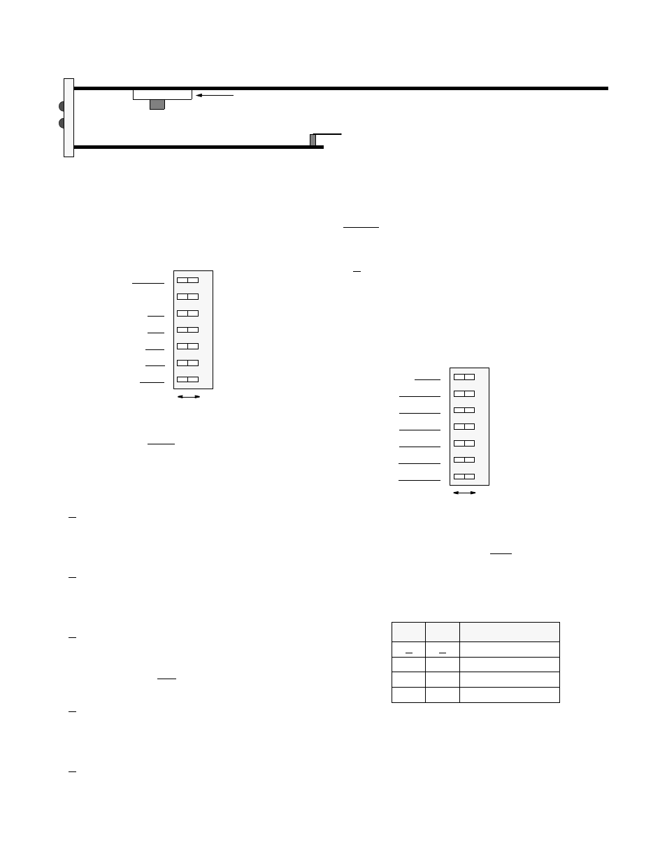
2.5.1
Configuration Switch S1
Front panel Switch S1 provides the following configuration
parameters.
S1 -1:
This switch position sets the ESF operating mode
for the unit. In the 54016 mode, the unit responds only to
54016 CSU messages. In the T1.403 mode, the unit
responds to ANSI loop /unloop commands and generates a
PRM every second, but will not respond to 54016 messages.
The two modes are exclusive of each other.
A - 54016
B - T1.403
S1 -2:
This position sets the network line coding, includ-
ing conversion.
A - AMI
B - B8ZS
S1 -3:
This position sets the DTE line coding, including
conversion.
A - AMI
B - B8ZS
S1 -4:
This position sets the CSU to the framing of the
network line. In the ESF mode, the unit responds to all
T1.403 or 54016 messages.
A - ESF
B - D4
S1-5:
This position sets the CSU to the framing of the
DTE line.
A - ESF
B - D4
S1-7:
This position controls the zero suppression mode.
Enabled allows ones density control after 15 successive
zeros from the DTE per TR62411. Disabled ignores density
control and allows 175 zeros to pass towards the network.
A - Enabled
B - Disabled
2.5.2
Configuration Switch S2
Front panel Switch S2 provides the following configuration
parameters.
S2 -1, S2-2: These two positions set the network line build
out signal level of data transmitted towards the T1 facility.
The output level is factory set at 0 dB. It may be attenuated
by -7.5 dB, -15 dB, or -22.5 dB if operating conditions
require a change. The telco should provide the proper setting
to the user.
If unsure, then leave it at the default setting of 0
dB.
S2 -3, S2-4, S2-5: These three positions set the DTE line
build out transmit signal value towards the customer equip-
ment. The value should match the cable length from the
CSU DTE port to the attached equipment.
B
A
Density - Enabled
Not used
DTE framing - ESF
NET framing - ESF
DTE code - AMI
NET code - AMI
Op Mode - 54016
Density - Disabled
Not used
DTE framing - D4
NET framing - D4
DTE code - B8ZS
NET code - B8ZS
Op Mode - T1.403
5
4
3
2
1
6
7
S2-1
S2-2
Network LBO Level
A
A
0 dB
A
B
-7.5 dB
B
A
-15.0 dB
B
B
-22.5 dB
NET LBO
NET LBO
DTE LBO
DTE LBO
DTE LBO
Pass received data
PRM disable
5
4
3
2
1
6
7
NET LBO
NET LBO
DTE LBO
DTE LBO
DTE LBO
AIS generation
PRM enable
B
A
Factory set -
TX
KX
Alarm Relay
Optional Alarm Card
do not change
Figure 2-1
Circuit Board View
Contacts