Operation, 0 introduction, 1 front panel descriptions – Verilink 2010 (34-00204) Product Manual User Manual
Page 12
Operation
3-1
2010 CSU
Operation
3.0
Introduction
This chapter describes the front panel operation and test fea-
tures of the TxPORT 2010 ESF CSU. These controls and
indicators are described below. A section is also included
describing the performance statistics which are collected
when the 2010 is on the far end of a TxPORT product with
an embedded terminal interface.
3.1
Front Panel Descriptions
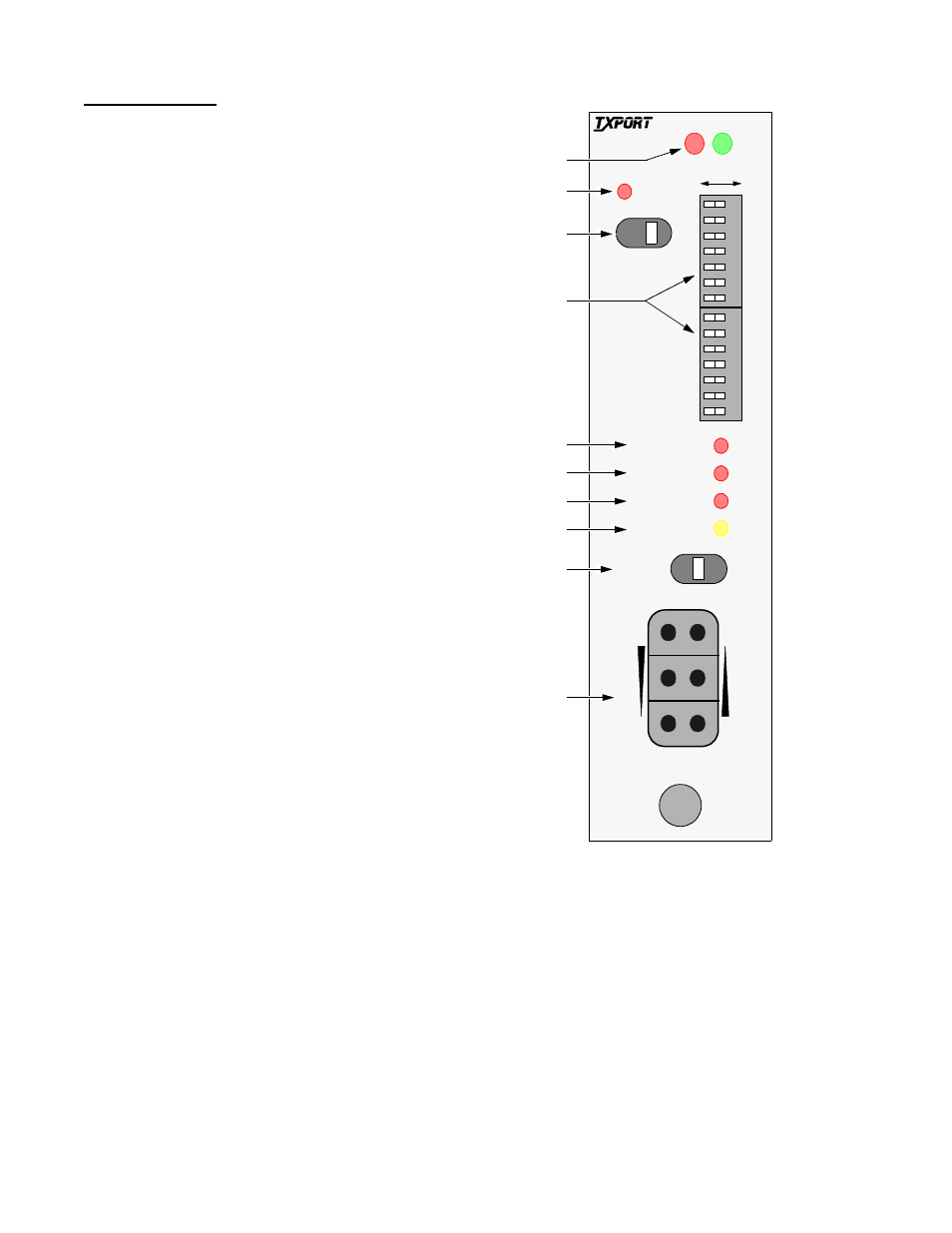
This section describes the controls and indicators found on
the 2010 CSU front panel. The unit uses LEDs to convey
major alarm conditions and looping status, a network test
switch, and test jacks. The two DIP configuration switches
are described in
Section 2.5 on page 2-1
. The following
descriptions are indexed to
.
3.1.1
General Status Indicators
1)
STATUS: The CSU has two LED indicators on the
front panel bezel that are exposed whether the access door is
open or closed. These general status LEDs provide a quick
check of the CSU’s operating condition (Go or No Go).
The green LED lights when the unit is powered and operat-
ing normally. The red LED lights if the alarm card circuitry
detects an alarm condition from the FAR, NET, or DTE
indicators or if an alarm threshold has been exceeded (if
equipped with optional alarm card). The green LED shuts
off if the red LED is on.
3.1.2
Alarm Controls and Indicators
2)
ACO: This red LED (only on units equipped with the
optional alarm card) lights if the ‘alarm cut off’ switch is
placed in the left ‘on’ position. It indicates that the alarm
relay contacts are disabled.
3)
ACO SW: This switch controls the alarm relay cir-
cuitry. This circuitry is deactivated in the left ‘on’ position.
The right ‘off’ position enables alarm reporting.
4)
NET ERROR: This LED lights a minimum of 0.1
second if the internal alarm circuitry detects any of the fol-
lowing conditions from the incoming T1 signal: one or
more BPVs, FBEs, CRCs, or loss of signal/loss of sync.
5)
FAR ERROR: This LED lights a minimum of 0.1 sec-
ond if the internal alarm circuitry detects a remote (yellow)
alarm signal from the far end terminal equipment. This con-
dition occurs if the far end terminal is out of sync with the
T1 signal from the network. The format for a remote alarm
is bit 2 set to 1 in each DS0 (D4 mode) or 8 ones/8 zeros in
the facility data link (ESF mode).
6)
DTE ERROR: This LED lights a minimum of 0.1
second if the internal alarm circuitry detects any one of the
Figure 3-1
2010 CSU Front Panel
ACO SW
ACO
Described in
3
NET ERR
1
7
6
5
4
3
2
1
S1
NRM
LOOP
2
7
6
5
4
3
2
1
S2
6
FAR ERR
DTE ERR
LOOP
8
FRM
NET
MON
TO
DTE
TO
NET
MON
FRM
DTE
9
A
B
2010
ESF CSU
‘Installation’
chapter
5
4
7
T
R
A
N
S
P
O
R
T
®