Installation on the tile interior – Upsite 1010 Integral Grommet User Manual
Page 3
3
Designer & Manufacturer
(888) 982-7800 www.upsite.com
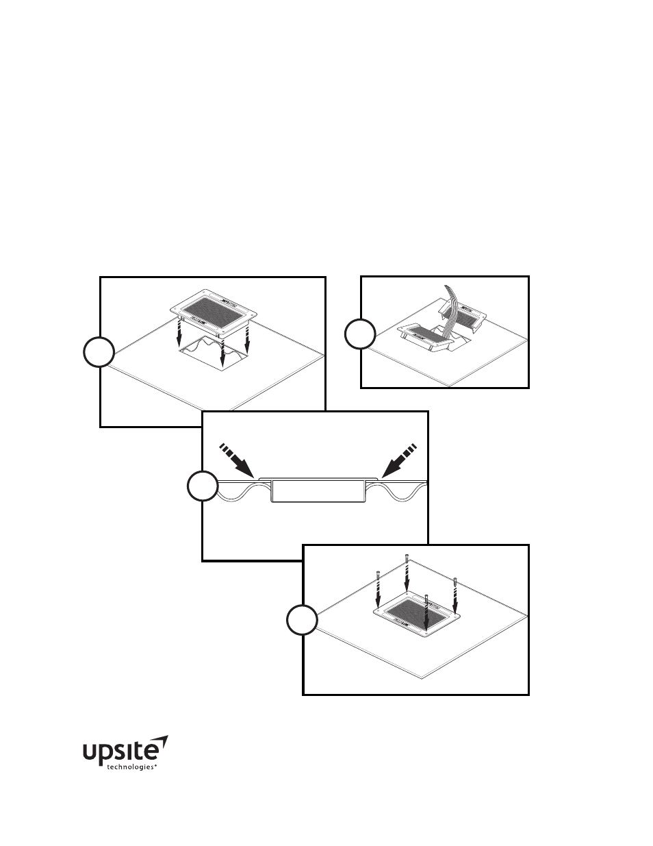
Installation on the Tile Interior
1. Make a 9 ¼” x 6 ¾” cutout (235mm x 172mm) in the floor tile. Ensure that any burrs
that resulted from cutting the floor tile have been removed. It is not necessary to dress
the cutout when installing a KoldLok Integral or Split Integral Raised Floor Grommet.
2. Test-fit KoldLok to the floor tile by making the flange flush with the topside of the floor
tile. Ensure there is no binding and that the fit is even on the Grommet.
3. With the Grommet properly placed in the floor tile, fasten it securely to the floor tile
using the self-tapping screws. Do not over-torque the screws.
Dimensions and Tile Cutting Requirements
Inches (W x D x H)
Millimeters (W x D x H)
Part No. 1010 & 3030 - Overall size
11” x 8 1⁄4“ x 1 5⁄8“
279 x 210 x 41mm
Product height above the raised floor
1⁄8”
3mm
Usable cable area
8” x 4”
203 x 102mm
Cut required to install Grommet
in interior of the tile
9 1⁄4” x 6 3⁄4”
235 x 172mm
Cut required to install long side of
the Grommet on the tile edge
9 1⁄4” x 7 1⁄2”
235 x 191mm
Cut required to install short side of
the Grommet on the tile edge
6 3⁄4” x 10 1⁄4 “
172 x 260mm
1-888
-982-
7800
www
.koldlo
k.com
U.S. P
aten
t No
. 6,63
2,999
Inter
natio
nal P
aten
t Pen
ding
1-8
88-
982
-78
00
ww
w.ko
ldl
ok.c
om
U.S.
Pat
ent No
. 6,632,
999
Int
erna
tional P
aten
t Pending
1-888
-982-
7800
www
.koldlo
k.com
U.S. P
atent No
. 6,63
2,999
Inter
national
Paten
t Pending
1-8
88-
982
-78
00
ww
w.ko
ldl
ok.c
om
U.S. P
aten
t No
. 6,63
2,999
Int
erna
tional P
aten
t Pendi
ng
1
2
3
1-8
88-
982
-78
00
www
.ko
ldlo
k.co
m
U.S. P
aten
t No
. 6,63
2,999
Int
erna
tion
al Pa
ten
t Pen
ding
1-888-9
82-780
0
www.ko
ldlok.co
m
U.S. Paten
t No. 6,
632,
999
Interna
tional P
atent Pe
ndin
g
ALT