Tri Tool 214B Flange Facer User Manual
Page 10
10
TRI TOOL INC.
92-1503 : Orig. 100923
NOTE:
Check for the proper position of the Tool Bit to the flange. (Refer to "To adjust the
depth of cut of the Tool Bit to flange...." later in this section.)
Check the position of the Tripper Shaft for feed rate. (Refer to "Feed Rate" later in
the section.)
Attach the proper power supply line to the Model 214B.
Check that the air supply filter/regulator/lubricator (FRL) is installed and set
properly.
Turn the Motor on. (Refer to "Cutting Speeds and Feeds".)
The actual machining operation will begin when the cutting surface of the Tool
Bit comes in contact with the flange.
If the pipe end is not square to the pipe axis, the Tool Bit will contact only a
small segment of the flange during each revolution.
To avoid Tool Bit damage, the Tool Bit must clear the highest point of the
flange on the first revolution.
After the cut is finished, release the Air Motor Lever to stop the Cutting Head rota-
tion.
Loosen the Mandrel Draw Nut and remove the BEVELMASTER® from the pipe.
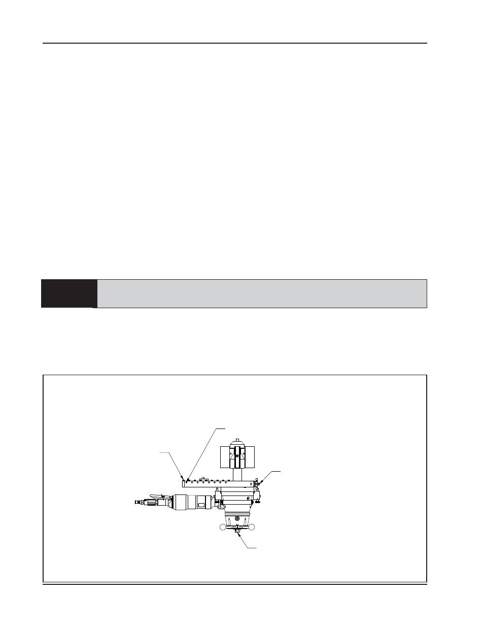
Location of the Various Screws
Hold Down
Screws
Adjustment
Set Screws
Feed
Sprocket
Mandrel Draw Nut