Installation procedures, Fo r us e as an ad just able co – Thermon FAK-4L Kit User Manual
Page 5
Specifi cations and information are subject to change without notice. Form PN50090U-1013
THERMON . . . The Heat Tracing Specialists
®
www.thermon.com
Corporate Headquarters
100 Thermon Dr.
•
PO Box 609
San Marcos, TX 78667-0609
•
USA
Phone: +1 512-396-5801
European Headquarters
Boezemweg 25
•
PO Box 205
2640 AE Pijnacker
•
The Netherlands
Phone: +31 (0) 15-36 15 370
For the Thermon offi ce nearest you
visit us at . . .
www.thermon.com
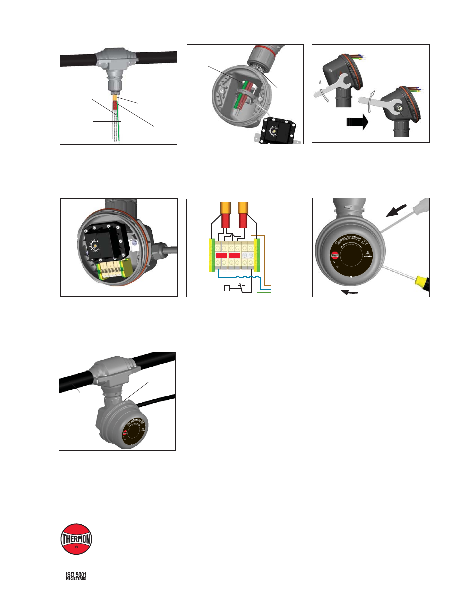
17.
Wiring Details:
Thermostat Connection
(1 or 2 Heating Cables)
Power Supply
L1
N
PE
Heat Trace #1
Heat Trace #2
2
2
4 L1
N
N
PE
PE
18.
Install junction box lid and twist hand tight.
Insert screwdriver into ratchet slot located
on side of junction box base to tighten. Use
screwdriver ratchet on junction box lid. Lid will
rotate 30°. To remove lid, repeat steps but in
opposite direction.
19.
Completed Terminator ZT/FAK-4L power/
thermostat assembly for TubeTrace Type SE/
ME Bundle (Installation shown is to feed power
in the middle of a TubeTrace bundle. Many
installations will be near the end of a TubeTrace
bundle.) Install bundle clamps (order seperately)
300mm before and after In-line power kit.
30º
Tubing Bundle
Junction Box
14.
Mount junction box on expediter making sure to
align slots to properly orient junction box base.
Tighten nut with Terminator-LN-Tool.
Align Slot
Grommet
Compressor
15.
Remove M25 dust cap. Install M25
power gland (order seperately) and
M25 blind plug.
16.
Install thermostat and complete system
wiring. Terminal set screws shall be tightened
to a torque value of 1.4 Nm (12.4 lb-in). See
step 17 for wiring details. Set thermostat at
desired setpoint.
INSTALLATION PROCEDURES
4
17
25
I
I 2
GD
Ex d
b eb IIC
T5-T6, Ex tb IIIC
T10
0°C
-T8
5°
C,
F
M
1
0A
TE
X0
0
5
8
X
IEC
Ex F
MG 1
0.0022X
Ex db
eb I
IC T
5-T
6,
Ex
tb
II
IC
T
10
0°
C
-T
8
5
°C
PN 27656
Te
rm
inator Z
T
Fo
r u
se
as
an
adj
ustable
control/lim
iter th
erm
ost
at
IP
6
6 -
60
°C
≤
Ta ≤
+50
°C T5, 100°C; -60°C ≤
Ta
≤
+4
0°
C
T6
, 8
5°
C
17
25
II
2 G
D Ex d
b eb IIC T5-T6, Ex tb I
IIC
T1
00
°C
-T
85
°C
,
F
M
1
0
A
T
E
X
0
0
5
8
X
IECE
x FMG
10.0022X Ex d
b e
b I
IC
T
5-
T6
, E
x
tb
I
II
C
T
1
0
0
°C
-T
8
5
°C
PN 27656
Te
rm
ina
tor ZT
Fo
r
us
e
as
an
ad
just
able co
ntr
ol/limiter t
herm
osta
t
IP
66
-6
0°C
≤ T
a ≤ +
50°C T5, 100°C; -60°
C ≤
Ta
≤
+
4
0
°C
T
6
,
8
5
°C
13.
Terminate heat tracing with appropriate PETK
termination kit. Refer to PETK installation
instructions for details not addressed here.
Tighten cap securely.
Power Connection
Boot
Heat Tracing
Ground Braid
Capillary