Terminator, Zt / fak-4l, Cb a – Thermon FAK-4L Kit User Manual
Page 2
The following installation procedures are suggested
guidelines for the installation of the Terminator ZT / FAK-4L
Thermostat Connection In-Line Power Kit.
Receiving, Storing and Handling . . .
1. Inspect materials for damage incurred during
shipping.
2. Report damages to the carrier for settlement.
3. Identify parts against the packing list to ensure the
proper type and quantity has been received.
4. Store in a dry location.
Item Qty
Description
1
1
Expediter Assembly: Support Cap with O-Ring,
Threaded Grommet Compressor, Grommet, Support
Base with O-Ring
2
1
Junction Box Lid
3
1
Junction Box Base with O-Ring and M25 Dust Cap
4
1
Expediter Nut
5
1
Thermostat w/ Terminal Blocks
(Refer to terminal specifi cations for maximum allowable wire size)
Thermostat Type
Control Range
ZT-C-100 0
°
C to +100
°
C
ZT-C-200 0
°
C to +200
°
C
ZT-C-300 0
°
C to +300
°
C
ZT-C-500 20
°
C to +500
°
C
6
1
Junction Box Cord
7
1
Bulkhead Entry Cover (Top)
8
1
Bulkhead Entry Base (Bottom)
9
1
Blind Plug
10
12
Pan Head S.S. Screws, #10-32 x 19mm
11
12
KEPT S.S. Nuts, #10-32
12
3
M5 Screw
13
3
M5 Lock Washer
14
1
Heat Refl ective Tape
15
1
Glass Fiber Tape
16
3
RTV Sealant Tube
17
2
Small Bundle Adapter
2
1
3
4
13
12
14
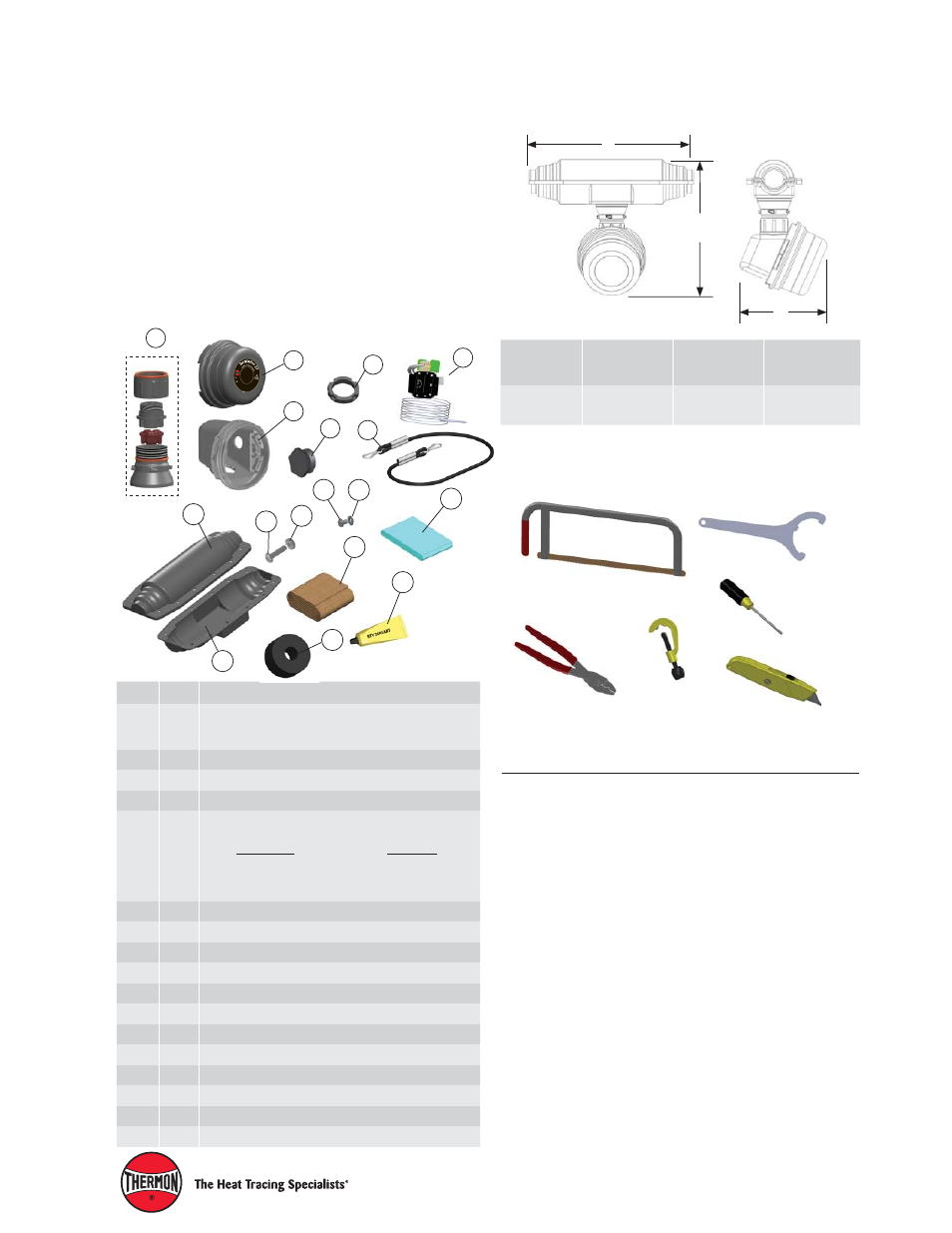
Tools Required . . .
Terminator ZT / FAK-4L Kit Contents . . .
6
5
7
15
16
1
Terminator
TM
ZT / FAK-4L
1
7
2
5
I
I 2
G
D
E
x d
b eb
IIC T
5-T6, Ex tb IIIC T100°C
-T8
5°C
, F
M
1
0A
TE
X
0
0
5
8
X
IE
C
Ex
FM
G 1
0.00
22X
Ex db eb IIC T5
-T6
, Ex
tb
II
IC
T
10
0
°C
-T
8
5
°C
PN 27656
Te
rminat
or
ZT
Fo
r u
se
as a
n adjus
table contro
l/lim
iter
th
erm
o
st
at
IP
6
6
-
6
0
°C
≤
Ta
≤
+5
0°C
T5, 1
00°C; -60°C ≤ Ta ≤
+4
0°
C
T6
, 8
5
°C
Dimensions . . .
C
B
A
A
inch (mm)
B
inch (mm)
C
inch (mm)
Terminator ZT
/FAK-4L
372 mm/14.6 in
308 mm/12.1 in
185 mm/7.3 in
17
10
11
8
9
Order Separately . . .
PETK Power and End Termination Kits (per cable)
PETK-1
for RSX, VSX, BSX
PETK-2
for KSX, HTSX
PETK-3-ZT
for HPT, FP
Terminator-LN-Tool
(order separately)