Terminator, Zt / fak-4l – Thermon FAK-4L Kit User Manual
Page 4
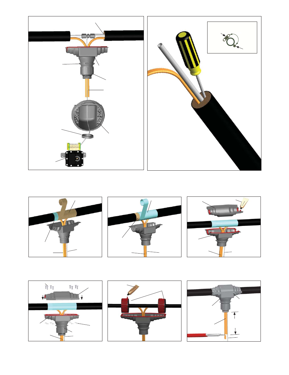
Thermostat Sensor
Bulkhead Entry Base
Expediter
Tracing Cable
Junction Box
Base
Thermostat
Expediter Nut
Weep Hole
6.
Route thermostat bulb through expediter nut and expediter opening in
junction box base. If necessary, apply lubricant (user supplied) to the end
of thermostat bulb. Slide through conical grommet hole. Insert the tracing
cables through conical grommet holes and punch out weep hole.
Thermostat
Sensor
180°
Heating Cable
(Typical)
Heating Cable vs. Sensor Location
7.
Create a gap between the insulation and the tube with a screw driver for the
sensor and place the sensor inside.
Terminator
TM
ZT / FAK-4L
Heat Tracing
Capillary
Heat Refl ective Tape
Glass Fiber Tape
8.
Wrap tube and heat trace with 1 pass of refl ective
tape (25% overlap), then wrap with 3 passes of
glass fi ber tape (50% overlap), or until fi ber tape
is equal to original bundle insulation thickness.
Heat Tracing
Capillary
Glass Fiber Tape
Heat Refl ective Tape
11.
Assemble splice cover top, tubing bundle, and
splice cover base together as shown, using
10-32 X 19mm pan head screws and KEPT
nuts.
Heat Tracing
Expediter Base
KEPT
Nuts
M5 Screws
Splice
Cover
Base
Splice Cover
Top
Capillary
9.
Complete with additional passes of heat refl ective
tape.
11a.
Place small bundle adapters as shown. Apply
RTV sealant to spacers liberally.
RTV
Sealant
Small Bundle
Adapters
180mm
Minimum
Heat Tracing
12.
Trim heat tracing to 180mm minimum from
expediter base.
Expediter Base
Splice Cover
Top and Base
Capillary
For Bundle Diameters Less Than 64 mm.
3
10.
Form a gasket by applying RTV sealant to splice
cover base and along radius of splice cover
top as shown.
Heat Tracing
Splice
Cover
Base
Splice Cover
Top
Capillary
RTV Sealant