Terminator, Zt-p-xp, Installation procedures – Thermon ZT-P-XP User Manual
Page 2
2
Item
Quantity
Description
1
1
RTV Tube
2
1
Power Connection Boot
3
2
Conductor Wire Pins
4
1
Braid Wire Pin
5
1
Ground Sleeve
6
1
End Cap
7
1
Tape Strip (PETK-3-ZT only)
8
1
Grommet (PETK-3-ZT only)
9
1
End Termination Caution Label
1
2
6
4
3
8
5
7
9
1
2
6
4
3
8
5
7
9
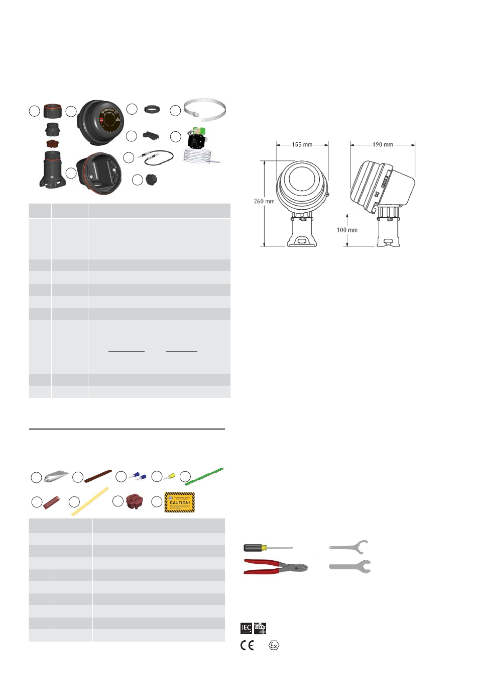
Item Quantity
Description
1
1
Expediter Assembly
Support Cap with O-Ring
Threaded Grommet Compressor
Grommet
Support Base with O-Ring
2
1
Junction Box Lid
3
1
Junction Box Base with O-Ring and M25 Dust Cap
4
1
Nut
5
1
Banding
6
1
Banding Guide
7
1
Thermostat w/ Terminal Blocks
(Refer to terminal specifi cations for maximum allowable wire size)
Thermostat Type Control Range
ZT-C-100 0
°
C to +100
°
C
ZT-C-200 0
°
C to +200
°
C
8
1
Junction Box Cord
9
2
Blind Plug
Ter
m
inato
r Z
T
IP66
-45°C
Ta
+ 55°C
For
use
as an adjustable co
ntro
l th
erm
os
ta
t
wi
th
The
rmon heating
ca
ble
s
ys
te
m
s
II 2 G & D E
Ex ed I
I C T5
0539
DEMKO 02A
TEX132552X
17
2
5
II
2 G
D E
x db e
b IIC T5-T6, Ex tb IIIC T
100
°C-
T8
5°
C,
F
M
1
0A
TE
X
0
0
5
8
X
IEC
Ex F
MG 1
0.0022X
Ex db
eb I
IC T
5-T
6,
Ex
tb
II
IC
T
10
0
°C
-T
8
5
°C
PN 27656
Te
rm
ina
tor Z
T
Fo
r u
se
as
an
adj
ustable
control/lim
iter t
her
m
os
tat
IP
6
6
-6
0°
C ≤
Ta
≤ +
50°C
T5, 100°C; -60°C ≤
Ta
≤
+4
0°
C
T6
, 8
5
°C
Kit Contents . . .
The following installation procedures are suggested
guidelines for the installation of the Terminator ZT-P-XP Kit.
Terminator
TM
ZT-P-XP
INSTALLATION PROCEDURES
Receiving, Storing and Handling . . .
1. Inspect materials for damage incurred during shipping.
2. Report damages to the carrier for settlement.
3. Identify parts against the packing list to ensure the
proper type and quantity has been received.
4. Store in a dry location.
Dimensions . . .
Warnings . . .
• Due to the risk of electrical shock, arcing and fi re
caused by product damage or improper usage,
installation or maintenance, a ground-fault protection
device is required.
• Installation must comply with Thermon requirements
(including form PN 50207U for Ex systems) and be
installed in accordance with the regulations as per the
norm EN IEC 60079-14 for hazardous areas (where
applicable), or any other applicable national and local
codes.
• Component approvals and performance ratings are
based on the use of Thermon specifi ed parts only.
• De-energize all power sources before opening
enclosure.
• Avoid electrostatic charge. Clean only with a damp
cloth.
• Keep ends of heating cable and kit components dry
before and during installation.
• Minimum bending radius of heating cable is 32 mm
(except HPT is 57 mm and FP is 19 mm).
• Individuals installing these products are responsible
for complying with all applicable safety and health
guidelines. Proper Personal Protective Equipment
(PPE) should be utilized during installation. Contact
Thermon if you have any additional questions.
• Consult the manufacturer for dimensional information
on the fl ameproof joints for repair.
Tools Required . . .
Terminator-LN-Tool
(order separately)
3 mm
8 mm
28 mm
Order Separately . . .
PETK Power and End Termination Kits (per cable)
PETK-1
for RSX, VSX, BSX
PETK-2
for KSX, HTSX
PETK-3-ZT
for HPT, FP
Certifi cations/Approvals . . .
1725 II 2 GD Ex db eb IIC T5-T6, Ex tb IIIC T100°C-T85°C FM10ATEX0058X
IP66; -60°C ≤ Ta ≤ +55°C T6, 85°C 16 Amps Max
-60°C ≤ Ta ≤ +50°C T5, 100°C 25 Amps Max
Ordinary & Hazardous Locations
FMG 10.0022X Ex db eb IIC T5-T6, Ex tb IIIC T100°C-T85°C