Installation instructions 3 – Thermon ZP-L-WP Terminator User Manual
Page 4
Installation Instructions
3
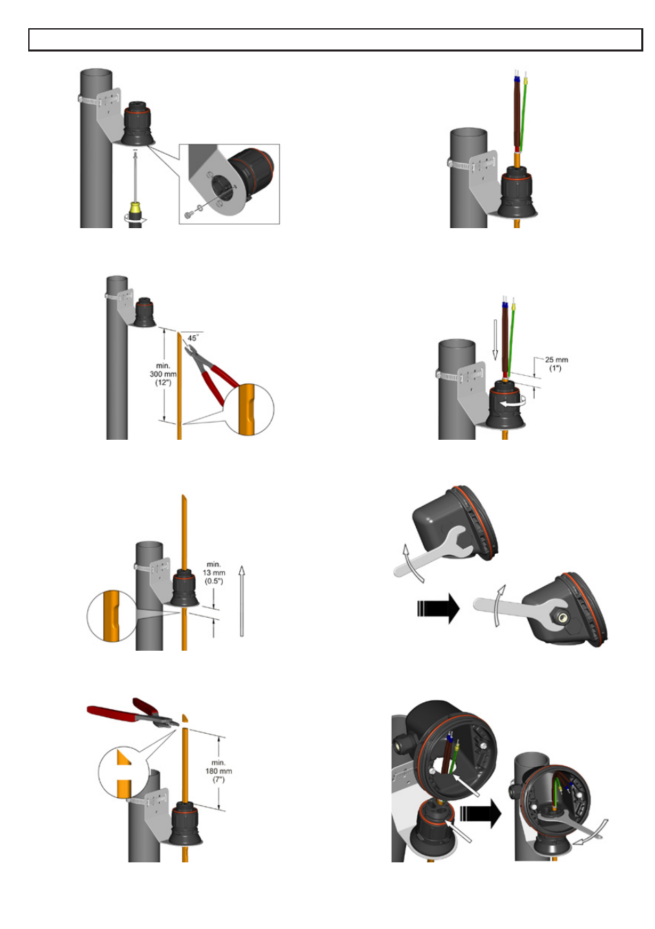
Mount junction box base on expediter. Make sure to align
slots to properly orient junction box base. Tighten nut with
Terminator-LN-Tool. If mounting horizontally, threaded gland
holes must face downward.
Install M25 power gland and M25 blind plug. For in-line
splice, T-splice, or end termination, install additional M25
blind plug (order M25-B-EXE separately) instead of M25
power gland.
9.
10.
6.
5.
7.
8.
Cut off end of cable.
Terminate cable with appropriate PETK termination kit.
Refer to PETK installation instructions.
Push excess cable back through expediter. Tighten cap
securely.
Insert cable into expeditor. Make sure bus connection (HPT
and FP only) remains outside of expediter.
3.
4.
Locate bus connection (HPT and FP only) as shown.
Cut end of cable at angle to aid in piercing grommet. Leave
additional cable for expansion as needed.
Mount expediter to bracket using M5 screws and lock
washers.