Kit contents 1, Warnings certifications/approvals, Tools required – Thermon ZP-L-WP Terminator User Manual
Page 2
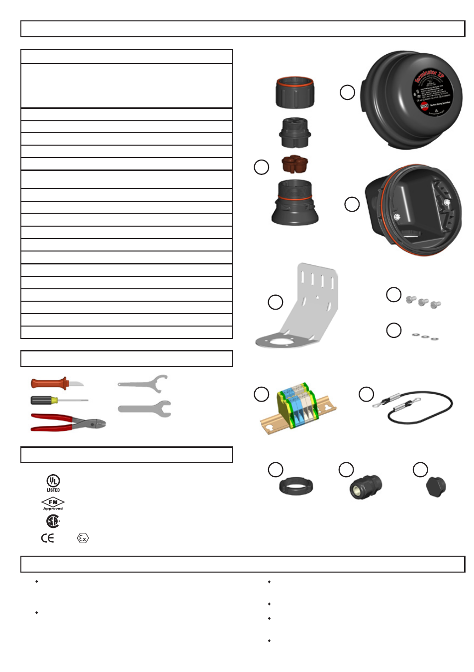
Kit Contents
1
Due to the risk of electrical shock, arcing and fire caused by
product damage or improper usage, installation or maintenance,
a ground-fault protection device is required.
Installation must comply with Thermon requirements and be
installed in accordance with the regulations as per the norm EN
IEC 60079-14 for hazardous areas (where applicable), or any
other applicable national and local codes.
Component approvals and performance ratings are based on the
use of Thermon specified parts only.
De-energize all power sources before opening enclosure.
Keep ends of heating cable and kit components dry before and
during installation.
Minimum bending radius of heating cable is 32 mm (except HPT
is 57 mm and FP is 19 mm).
Warnings
Certifications/Approvals
1
2
3
7
8
9
10
11
2
1
Junction Box Lid
Item Qty Description
Support Cap w/ O-ring
Threaded Grommet Compressor
Grommet
Wall Mount Support Base w/ O-ring
1
1
Expediter Assembly
3
1
Junction Box Base w/ O-ring
7
1
Terminal Blocks w/ DIN Rail
8
1
Junction Box Lid Cord
9
1
Nut
10
1
Power Gland
11
1
Blind Plug
12
2
Conductor Wire Pins
(per cable)
13
1
Braid Wire Pin
(per cable)
14
1
Power Connection Boot
(per cable)
15
1
Ground Sleeve
(per cable)
16
1
RTV Tube
(per cable)
Tools Required
Terminator-LN-Tool
(order separately)
3 mm
8 mm
28 mm
29 mm
33 mm
4
5
6
4
1
Wall Mount Bracket
5
3
M5 Screws
6
3
Lock Washers
17
1
IEK Insulation Entry Kit
(per cable)
18
1
to
2 Banding
(optional, see steps 2
-1
or 2
-3
)
19
1
XP-1 Bracket
(optional, see step 2
-3
)
IP66 NEMA/Type 4X -60°
C ≤ Ta ≤
+55
°C
Listed Heat Tracing Cable System 137M
Ordinary & Hazardous Locations
Class I, Division 2, Groups A, B, C & D
Class II, Division 2, Groups F & G, Class III
Class I, Zone 1, AEx e II T4-T6
Ex e II T4-T6
0539 II 2 G & D Ex e II T4-T6 DEMKO 06ATEX0622119