Petk, Installation procedures – Thermon PETK User Manual
Page 2
2
FMG 10.0022X Ex eb IIC T4-T6, Ex tb IIIC T135°C-T85°C
1725 II 2 GD Ex eb IIC T4-T6, Ex tb IIIC T135°C-T85°C, FM 10ATEX0058X
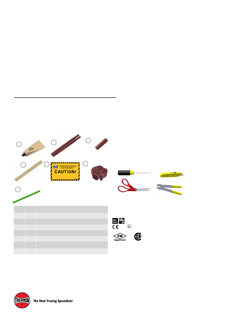
PETK Power and End Termination Kits (per cable)
PETK-1
for BSX, RSX, VSX
PETK-2
for KSX, HTSX
PETK-3
for HPT, FP
PETK-3-ECM
for HPT, FP
PETK-3-ZT
for HPT, FP
Receiving, Storing and Handling . . .
1. Inspect materials for damage incurred during ship-
ping.
2. Report damages to the carrier for settlement.
3. Identify parts against the packing list to ensure the
proper type and quantity has been received.
4. Store in a dry location.
1
2
Item
Qty.
Description
1
1
RTV Tube
2
1
Power Connection Boot
3
1
End Cap
4
1
Tape Strip (PETK-3 Only)
5
1
End Termination Caution Label
6
1
Grommet (For PETK-3 Terminator kits only)
7
1
Ground Sleeve
3
5
4
NOTE: This label is to have been placed over the end
termination of an electrical heat tracing circuit.
Electrical
lockout may be required before working on this line
or removal of thermal insulation.
6
Kit Contents . . .
7
Tools Required . . .
Note:
1. These sets have been evaluated as components of Thermon’s Approved con-
nection kits, such that the area use ratings depend on the rating of the connec-
tion kits.
PETK Certifications/Approvals
1
. . .
PETK
INSTALLATION PROCEDURES
Warnings . . .
• Due to the risk of electrical shock, arcing and fire
caused by product damage or improper usage,
installation or maintenance, a ground-fault protection
device is required.
• Installation must comply with Thermon requirements
(including form PN 50207U for Ex systems) and be
installed in accordance with the regulations as per the
norm EN IEC 60079-14 for hazardous areas (where
applicable), or any other applicable national and local
codes.
• Component approvals and performance ratings are
based on the use of Thermon specified parts only.
• De-energize all power sources before opening
enclosure.
• Keep ends of heating cable and kit components dry
before and during installation.
• Minimum bending radius of heating cable is 32 mm
(except HPT is 57 mm and FP is 19 mm).
• Individuals installing these products are responsible
for complying with all applicable safety and health
guidelines. Proper Personal Protective Equipment
(PPE) should be utilized during installation. Contact
Thermon if you have any additional questions.
The following installation procedures are guidelines for
the installation of the Power and End Termination Kit. For
translations other than English and local language translation
provided here, please contact Thermon. The English
language installation procedure shall govern.
Note:
Wire pins may be required as per client/project specification (order seperately).