Electric heat tracing, Installation on valves and pumps – Thermon Electric Heat Tracing User Manual
Page 6
Electric Heat Tracing
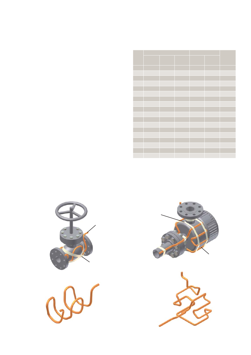
Heating Cable Serpentined on Valve
Circuit Layout on Pump
Heating Cable Serpentined on Pump
Attachment Tape
(Typical)
Heating Cable
Heating Cable
Attachment Tape
(Typical)
Circuit Layout on Valve
5
Installation on Valves and Pumps . . .
1. Install heating cable in accordance with Illustrations G and
H below. Secure heating cable to piping using attachment
tape.
2. Additional cable is required to provide extra heat at
valves, pumps and miscellaneous equipment to offset the
increased heat loss associated with these items. Refer to
Table 1 for estimated cable requirements for installation
on typical valves and pumps. Allowances shown in
Table 1 are for 150 pound valves. More cable is required
for higher rated valves. Refer to heat trace isometric
drawing for project specifi c allowances.
3. Install heating cable on valves and pumps utilizing a
looping technique (this allows the valve or pump to be
removed if required). Crossing constant watt heating
cable over itself should be avoided.
4. Refer to the product specifi cations sheet for minimum
bend radius for the specifi c cable type. Do not exceed
bend radius when completing installation.
Table 1: Valve and Pump Allowances
1
Illustration G: Typical Valve Detail
Illustration H: Typical Pump Detail
Pipe
Size
(mm)
Valve Allowance (M)
Pump Allowance (M)
Flange
Allowance
(M)
Screwed
or Welded
Flanged
Butterfl y Screwed
Flanged
12
0.20
0.30
0.00
0.30
0.61
0.38
20
0.20
0.46
0.00
0.46
0.91
0.46
25
0.30
0.61
0.30
0.61
1.22
0.46
32
0.50
0.61
0.30
0.91
1.37
0.61
40
0.50
0.76
0.46
0.91
1.52
0.61
50
0.60
0.76
0.61
1.22
1.68
0.69
80
0.80
1.07
0.76
1.52
2.13
0.69
100
1.20
1.52
0.91
2.44
3.05
0.84
150
2.10
2.44
1.07
4.27
4.88
0.99
200
2.90
3.35
1.22
5.79
6.71
1.14
250
3.80
4.27
1.22
7.62
8.53
1.30
300
4.60
5.03
1.52
9.14
10.06
1.52
350
5.50
5.94
1.68
10.97
11.89
1.68
400
6.60
7.01
1.83
13.11
14.02
1.83
450
7.80
8.23
1.98
15.54
16.46
1.98
500
8.70
9.14
2.13
17.37
18.29
2.21
550
10.40
10.97
2.44
20.73
21.95
2.51
600
12.20
12.80
3.05
24.38
25.60
3.05
Note . . .
1. The valve allowance given is the total amount of additional cable to be installed on
the valve. If multiple tracers are used, total valve allowance may be divided among
the individual tracers. The total valve allowance may be alternated among tracers for
multiple valves in a heat trace circuit. Allowances are for 150 pound valves. More
cable is required for higher rated valves. Refer to heat trace isometric drawing for
project specifi c allowances.