Teletronics WINC2400C User Manual
Page 11
11
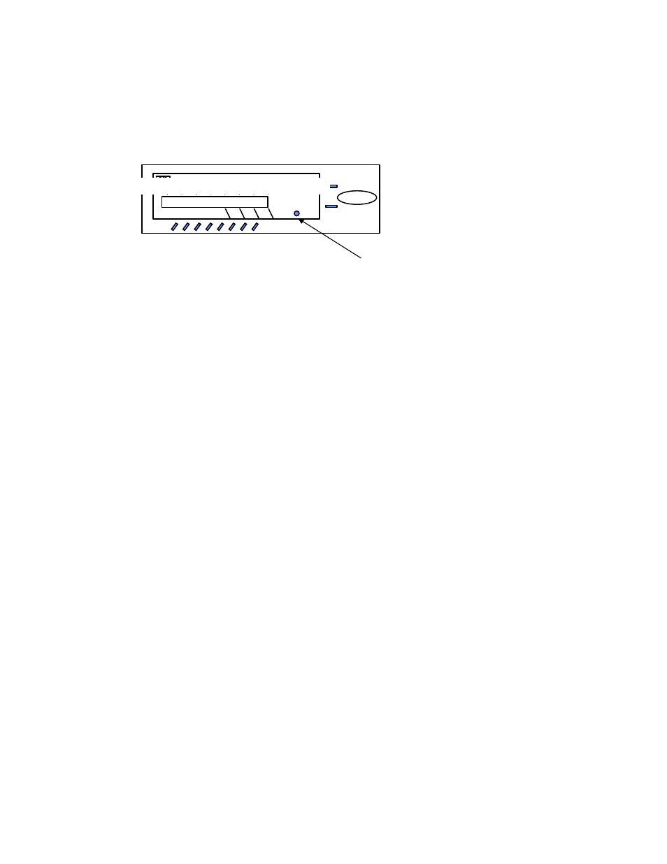
Whenever you need to clear the settings, you can issue AT command AT&F to reset the WINC
2400C to the original factory default conditions. An alternative method for accomplishing this is
to hold the reset button on the front panel and turn on the power of WINC 2400C. (please refer
to Fig. 5 -1) A pencil, pen or other sharply pointed object is required to access the button
through the hole on the front panel.
Step 4: Save the configuration settings
of your communications of software
If you already completed the steps above without problems, you may select the “Save” from the
“File” option in the MS-Windows Terminal and save the configuration settings for the future
before you leave Terminal.
If you still have problems communicating with the WINC 2400C from your computer, please check the
followings steps, and then start all over again from the beginning of this chapter.
1.
Contact your computer hardware engineer, verify the availability of the serial port (com port) on
your computer, and working on this until the serial port is available to you.
2.
Connect your serial port with an external land line modem and work on the communication software
setting until you get the dial tone, dialing out successfully.
3.
Replace the external modem with WINC 2400C. At this point, go through the factory default
setting process above to make sure that 9600 is the default baud rate on WINC 2400C.
4.
Please work from the beginning of chapter 4.0 again.
5.
If you still have problems communicating with the WINC 2400C, Please visit our Web Customer
Support page at www.teletronics.com or fill out the technical support request form at the last
page with all details and fax it to our “Technical Support Team” located in our US headquarters.
5.1 The Concept of Synchronous Configuration
After we have achieved the part I of the system configuration, we now move part II. Let us start with a
point-to-point link where two WINC 2400C are involved. Major technical
details are :
1. The Baud Rate setting of the external device.
2. Make sure that all external devices are configured as DTE and does take Tx and Rx clock from
external device -- WINC 2400C for better performance.
3. The interface configuration on the external device -- RS-232, RS-422, or V.35.
4. The frequency interference, LOS (line of sight) at both locations.
5. The address of both WINC 2400Cs.
(The seven (7) digit address is on the label affixed to the left side of the unit and is defined by the right-
most seven (7) digits of the serial number).
The configuration process is mainly a process of setting up parameters so that link can be maintained at
both WINC 2400Cs. Consistency includes the following.
T eletronics W i r e l e s s M o d e m
FULL DUPLEX INTERFACE
Power
Default
W inc 900C
ASYNC. PORT
SYNC. PORT
DCD
DTR
DSR
CTS
RTS
RxD
TxD
RTS
RxD
TxD
LINK
Fig 5-1. WINC 2400C Front Panel