Led setting – Sundance SMT365E User Manual
Page 13
Version 2.1
Page 13 of 26
SMT365e User Manual
LED Setting
The SMT365e has 13 LEDs. One shows the FPGA configuration status and the other
4 are under DSP control.
LED D6 always displays the state of the FPGA DONE pin. This LED is off when the
FPGA is configured (DONE=1) and on when it is not configured (DONE=0).
This LED should go on when the board is first powered up and go off when the FPGA
has been successfully programmed (this is the standard operation of the boot code
resident in the flash memory device). If the LED does not light at power-on, check
that you have the mounting pillars and screws fitted properly. If it stays on, the DSP
is not booting correctly, or is set to boot in a non-standard way.
Four of the remaining LEDs can be controlled with the LED register (D11, D12, D13,
D14). Writing 1 will illuminate the LED; writing 0 will turn it off.
Note that the LEDs D7-D10 are not used.
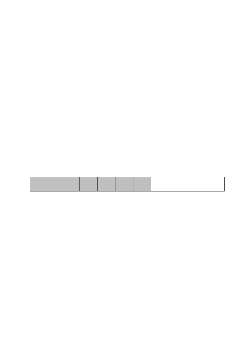
LED Register
(0x900D0000)
31–4
7 6 5 4 3 2 1 0
LED
D11
LED
D12
LED
D13
LED
D14
RW,0 RW,0 RW,0 RW,0 RW,0 RW,0 RW,0 RW,0
The four remaining LEDs (D2-5) are connected to the C60’s GPIO pins 12-15.