Interrupt control register, Vidin ie, Table 7: interrupt control register – Sundance SMT319 User Manual
Page 26
Version 1.0.7
Page 26 of 45
SMT319 User Manual
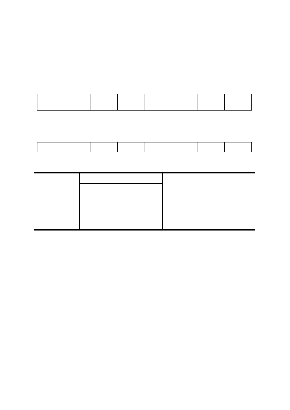
Interrupt Control Register
The Interrupt Control register is described in the general firmware description [7].
The register has been slightly modified to integrate video input and output
functionalities:
31–30 29–28 27–26 25–24 23–22 21–20 19–18 17–16
SDB0 IE VIDIN IE SDB2 IE
VIDOUT
IE
SDB4 IE SDB5 IE SDB6 IE SDB7 IE
RW,00 RW,00 RW,00 RW,00 RW,00 RW,00 RW,00 RW,00
15–14
13–12
11–10
9–8 7–6 5–4 3–2 1–0
SDB8 IE SDB9 IE SDB10 IE SDB11 IE SDB12 IE SDB13 IE SDB14 IE SDB15 IE
RW,00 RW,00 RW,00 RW,00 RW,00 RW,00 RW,00 RW,00
Field
Description
Interrupt condition selected
SDBx IE (bit 0) SDB IFLAG Interrupt Enable
≥ IFLAGLEVEL words available
SDBx IE (bit 1) SDB OFLAG Interrupt Enable ≥ OFLAGLEVEL spaces available
VIDIN IE (bit 0) VIDIN IFLAG Interrupt Enable ≥ IFLAGLEVEL words available
VIDOUT IE (bit
1)
VIDOUT OFLAG Interrupt
Enable
≥ OFLAGLEVEL spaces available
Table 7: Interrupt control register
VIDIN IE bit 1 and VIDOUT IE bit 0 are not implemented.