13 application example – Sundance SMT349 User Manual
Page 31
Version 2.1
Page 31 of 32
SMT349 User Manual
13 Application Example
SMT370
DAQ
Module #2
SMT349
Module #4
SMT310Q
PC
Host
Data
SDB
Connection
Control
Comm
Port
Data
Comm
Port
Analogue
Connection
Antenna
TIM site 2
TIM site 4
Data
SHB
Connection
Data
Global Bus
Connection
SMT349
Module #3
TIM site 3
SMT395
DSP Module
Module #1
TIM site 1
SMT596
MMBX
MMBX
MMBX
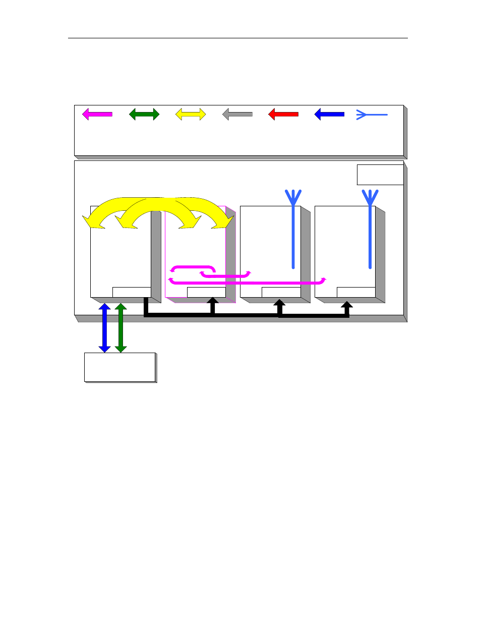
Figure 6 System example
The diagram shows an example of a system where an SMT310Q carrier board has
four modules plugged on it. The first module, SMT395 will be controlling the data
from/to the second module SMT370 via SHB connectors. The host application will
configure the SMT370 to generate a pattern of 16MHz sinusoidal signal sampled at
54 MHz such that a replica centred around 70MHz is also generated. (similar case as
the one shown in to figure 3). This signal is sent via MMBX-MMBX coaxial cable to
one of the SMT349s configured as transmitter. The last module, configured as
receiver, will pass the received signal back to the SMT370 via another MMBX-MMBX
coaxial cable and from there to the host through the SMT395.