12 control register settings – Sundance SMT349 User Manual
Page 19
Version 2.1
Page 19 of 32
SMT349 User Manual
11.1
FPGA configuration
You can configure the FPGA by programming the PROM via the JTAG connector
using for instance the Xilinx parallel cable IV.
12 Control Register Settings
The Control Registers control the complete functionality of the SMT349. They are set
up via the Comport 3. The settings of the IF/RF synthesizer, attenuators and RF
switches can be configured via the Control Registers.
12.1 Control Packet Structure
The data passed on to the SMT349 over the Comport must conform to a certain
packet structure. Only valid packets will be accepted and only after acceptance of a
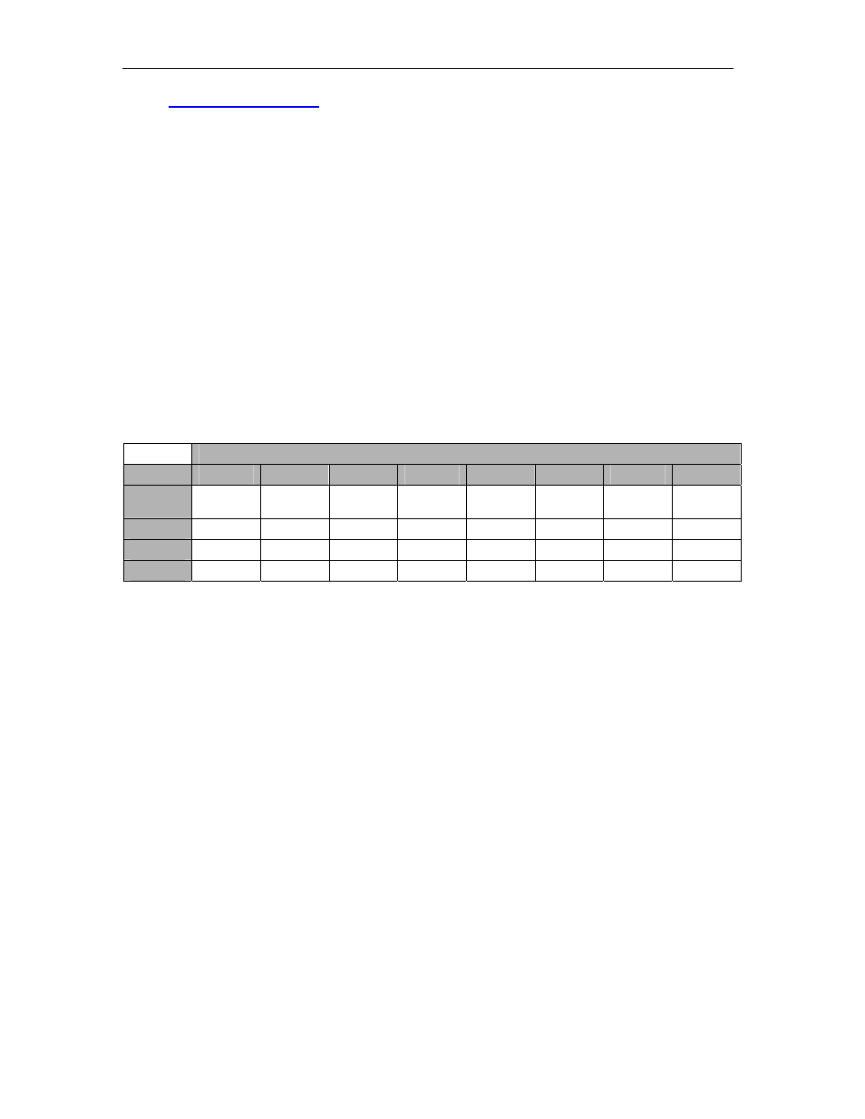
packet will the appropriate settings be implemented. Each packet will start with a
command (4 bits – 0x1 for a write operation – 0x2 for a read operation) information,
followed by a register address (8 bits), followed by a 20-bit data. This structure is
illustrated in the following figure:
Byte
Content
Byte
Bit 7
Bit 6
Bit 5
Bit 4
Bit 3
Bit 2
Bit 1
Bit 0
3
Command
3
Command
2
Command
1
Command
0
Address 7
Address 6
Address 5
Address 4
2
Address 3
Address 2
Address 1
Address 0
Data 19
Data 18
Data 17
Data 16
1
Data 15
Data 14
Data 13
Data 12
Data 11
Data 10
Data 9
Data 8
0
Data 7
Data 6
Data 5
Data 4
Data 3
Data 2
Data 1
Data 0
Table 2- Setup Packet Structure
12.2 Reading and Writing Registers
Control packets are sent to the SMT349 over Comport 3. This is a bi-directional
interface. The format of a ‘Read Packet’ is the same as that of a write packet.