Sundance SMT349 User Manual
Page 24
Version 2.1
Page 24 of 32
SMT349 User Manual
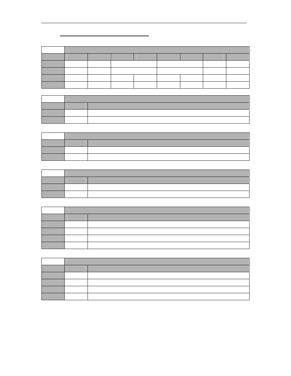
12.4.4 IF/RF Synthesizer Register 0 – 0x3.
For more details, refer to Si4136 datasheet.
IF/RF Synthesizer Register 0 – 0x03
Byte
Bit 7
Bit 6
Bit 5
Bit 4
Bit 3
Bit 2
Bit 1
Bit 0
1
Reserved Reserved
AUXSEL
IFDIV
Reserved Reserved
Default
‘0’ ‘0’
‘00’
‘00’
‘0’ ‘0’
0
Reserved
XIN DIV2
LPWR
Reserved
Auto PDB
Reserved
Reserved
Reserved
Default
‘0’ ‘0’ ‘0’ ‘0’ ‘0’ ‘0’ ‘0’ ‘0’
IF/RF Synthesizer Register 0 – 0x03
Setting
Bit 3
Description – Auto PDB (Auto power Down)
0
0
Software powerdown is controlled by IF/RF Synthesizer Register 2.
1
1
Equivalent to setting all bits in IF/RF Synthesizer Register 2 to ‘1’.
IF/RF Synthesizer Register 0 – 0x03
Setting
Bit 5
Description – LPWR (Power level for IF Synthesizer Circuit)
0
0
Rload < 500 Ohms – Normal Power Mode.
1
1
Rload > 500 Ohms – Low Power Mode.
IF/RF Synthesizer Register 0 – 0x03
Setting
Bit 6
Description – XIN DIV2 (Divide by 2 Mode)
0
0
Xin not divided by 2.
1
1
Xin divided by 2.
IF/RF Synthesizer Register 0 – 0x03
Setting
Bit 11&10
Description – IFDIV (IF output divider)
0
‘00’
IFout = IFvco frequency.
1
‘01’
IFout = IFvco frequency/2.
2
‘10
IFout = IFvco frequency/4.
3
‘11’
IFout = IFvco frequency/8.
IF/RF Synthesizer Register 0 – 0x03
Setting
Bit 13&12
Description – AUXSEL (Auxiliary Output Pin Definition)
0
‘00’ Reserved.
1
‘01’ Force
Output
Low.
2
‘10 Reserved.
3
‘11’
Lock Detect (LDETB).