Figure 4 - overview of data transfer mechanism – Sundance SMT6035 v.2.2 User Manual
Page 21
Version 2.2
Page 21 of 39
SMT6035 User Manual
DSP DMA
engine
Host PCI memory space
SRAM
Global bus
PCI Bridge
chip
Root TIM
Your application running on
host system
Carrier board
Local bus
Host system
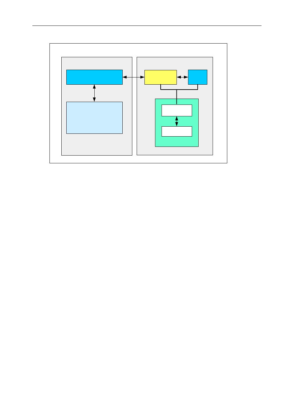
Figure 4 - Overview of data transfer mechanism
The SRAM on the carrier board is divided into 8 same-size sections, each
representing a high-speed channel. Each section contains:
• The memory descriptor list for any PCI memory associated with this
channel.
• Arguments (parameters) associated with this channel. Used as a shared
memory region between the host and the root DSP.
Note - The host application can gain access to the SRAM on the carrier board,
because the SRAM is mapped into the virtual memory space of the host
application. This is taken care of by the PCI bridge chip.
On the DSP side, 3L Diamond
©
provides built-in support for the HSC.
There are three mechanisms used to transfer data between the host and the
root DSP.
• Control words.
• SRAM arguments.
• PCI memory access.
User Manual - Version 2.2, 04/01/07; © Sundance Italia S.R.L.