Model 742 – Studio Technologies 742 2005 User Manual
Page 19
Model 742 User Guide
Issue 2, May 2005
Studio Technologies, Inc.
Page 19
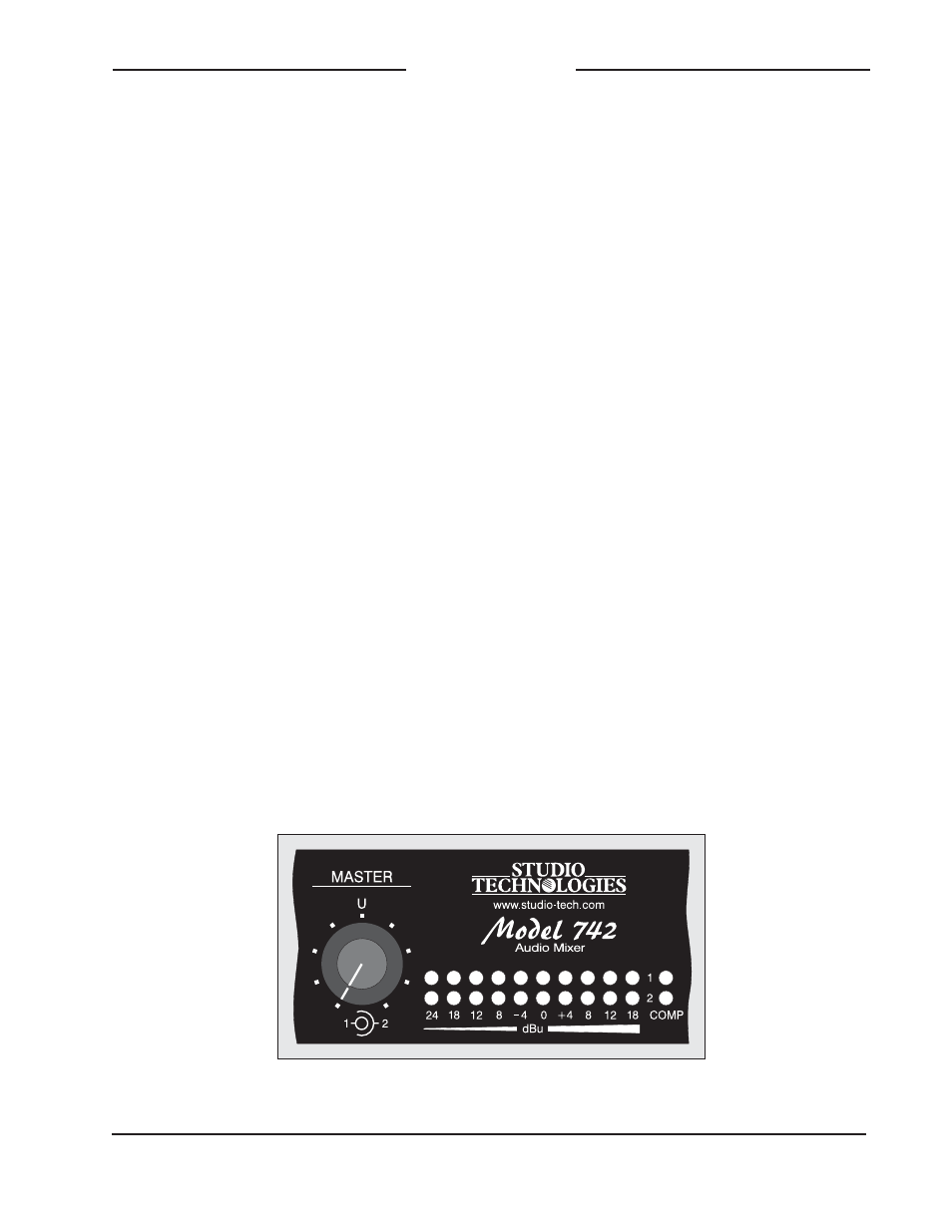
Model 742
Master Section/Main Output
Buses
The Model 742’s master section supports
output buses 1 and 2 with several controls
and switches, compressor circuitry, and
level and status indications. The following
sections provide detailed descriptions of
each of them.
Master Level Controls
Two rotary controls are used to set the
overall level of output buses 1 and 2. The
controls are “concentric” type, with the
inner knob controlling bus 1 and the outer
knob controlling bus 2. On the front panel,
note the graphic symbol and the letter
“U,” located at the “12-o’clock” rotational
position. This indicates the correct setting
to provide unity gain through the circuitry,
and is the position where the controls
should normally be set.
Compressor
Studio-quality compressor circuits are
associated with the two output buses. A
yellow LED, located to the right of each
LED meter, will light whenever its respec-
tive compressor is controlling the dynamic
range of the output bus. The operating
threshold of the compressors and associ-
ated LEDs depends on how the Model 742
has been configured:
• From the factory the compressor
thresholds are set to be 6 dB over the
Model 742’s nominal output level of +4
dBu. This correlates to a level on the
main output connectors of +10 dBu.
• The compressors’ configuration can
also be revised so that thresholds of 2
dB over nominal are selected. This cor-
relates to a nominal level on the main
output connector of +6 dBu. With this
configuration the compressors may be
active quite frequently during typical
Model 742 operation.
• A third configuration is also available
which serves to disable the compres-
sors. In this case dynamic range control
will never take place and the LEDs will
never light.
If the compressors are set to use one of
the two thresholds, i.e., +10 or +6 the
compressor active LEDs should prove
useful. With the input and master level
controls set correctly, the compressor
active LEDs will typically light only when
peak signals are present. In an “ideal”
Detail of front panel highlighting master level controls, 10-segment LED level meters, and compressor
active LEDs