Model 742, Monitor outputs, Reference tone direct output – Studio Technologies 742 2005 User Manual
Page 13
Model 742 User Guide
Issue 2, May 2005
Studio Technologies, Inc.
Page 13
Model 742
The main outputs utilize 3-pin male XLR-
type connectors for interconnection. Pre-
pare the mating connectors (females) so
that pin 2 is signal high (+ or hot), pin 3 is
low (– or cold), and pin 1 is shield. Wheth-
er these outputs are wired via a patch bay
will depend on the specific installation. But
at least having “mults” of the main outputs
on patch points is probably a good idea.
While balanced operation is generally
preferred, unbalanced operation is not a
problem for the output circuitry. To con-
nect to unbalanced loads prepare the
mating connectors so that pin 2 is high (+
or hot), and both pins 1 and 3 are shield.
For optimal unbalanced operation, it is
important to connect pins 1 and 3 together
directly on the connector that mates with
the Model 742, not at the other end of the
cable.
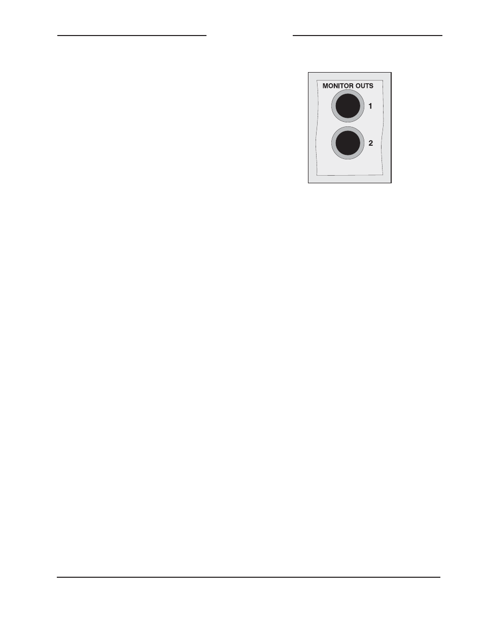
Monitor Outputs
The monitor outputs are designed to
connect to a variety of devices. In some
applications they will connect to an audio
power amplifier associated with a set of
monitor loudspeakers. In mobile applica-
tions it’s popular to use loudspeakers with
an internal amplifier, such as those from
Fostex. And, depending on how the moni-
tor outputs are internally configured, they
can also serve as a second set of +4 dBu
nominal main outputs.
The monitor outputs are electronically bal-
anced, capacitor coupled, and line-level.
They can drive balanced or unbalanced
loads of 600 ohms or greater. Configura-
tion jumpers allow the monitor outputs
to be set from among three operating
modes. In the “post” mode the output
levels are dependent upon the settings
of the front-panel level controls. In the
“pre –10” mode the monitor outputs have
a fixed nominal output level of –10 dBu.
In this mode, the nominal output level
has been optimized to match the input
sensitivity typically found on amplified
loudspeakers. In the “pre +4” mode the
monitor outputs have a fixed nominal
output level of +4 dBu.
The monitor outputs utilize ¼-inch
3-conductor jacks for interconnection.
Prepare the mating connectors (plugs)
so the tip is signal high (+ or hot), ring
is low (– or cold), and sleeve is shield. To
connect to an unbalanced load connect
tip to high (+ or hot) and both ring and
sleeve to shield. Whether or not these out-
puts are wired via a patch bay will depend
on the specific installation. In most cases
they will not be.
Reference Tone Direct Output
Direct access to a continuous source of
sine-wave reference tone is provided by
means of a line-level output. As one of
the unique features of the Model 742, it
should definitely be utilized! This output
is intended to be connected to an au-
dio input associated with a audio/video
switcher’s “bars and tone” position. For
maximum flexibility, it is recommended
that this signal be routed via a patch bay.
Detail of back panel showing
monitor output connectors