Model 742, Line inputs – Studio Technologies 742 2005 User Manual
Page 18
Issue 2, May 2005
Model 742 User Guide
Page 18
Studio Technologies, Inc.
Model 742
will light red as a peak signal indicator,
showing that the input signal, along with
the gain of the preamplifier, is within 6 dB
of the circuitry’s maximum level.
Level Control
The rotary control is used to adjust the
gain of the input section’s preamplifier
circuitry. It also controls the amount of
signal that can be sent to the output bus
(or buses). In the fully counterclockwise
position the preamplifier gain is set to its
minimum, and full attenuation to the bus
(or buses) is achieved. This means that no
signal continues on to the mixing circuitry
that creates the main outputs. As the level
control is rotated in the clockwise direc-
tion the gain of the preamplifier increases,
as does the level of the signal sent to the
selected output bus (or buses).
Output Assignment Switch
A 3-position toggle-type switch is used to
assign which of the output buses the sig-
nal will be routed to. In the “up” position
the signal is sent only to output bus 1. In
the “down” position the signal is sent only
to output bus 2. In the “center” position
the signal is sent to both output buses 1
and 2.
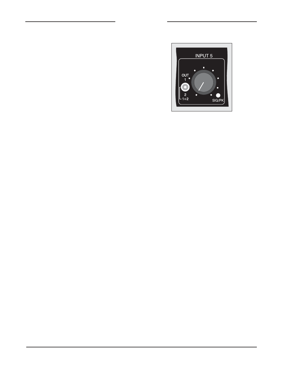
Line Inputs
Four identical line-level input channels
are provided. The following provides a
detailed description of one of them:
Status LED
A dual-color LED acts as a user-confi-
dence indication of the overall signal level
in the circuitry associated with the line-
level input. The LED will light green as a
signal present indicator, showing that the
input signal, along with the gain or loss of
the input amplifier, is at least 18 dB below
the nominal internal operating level. The
LED will light red as a peak signal indica-
tor, showing that the level is within 6 dB of
the circuitry’s maximum.
Level Control
The rotary control is used to adjust the
overall gain or loss of the line input’s
amplifier circuitry, thus setting the amount
of signal that is sent to the output bus
(or buses). In the fully counterclockwise
position the amplifier gain is set to its
minimum, and full attenuation is achieved.
This means that no signal continues on to
the mixing circuitry that creates the main
outputs. As the level control is rotated in
the clockwise direction the gain of the
preamplifier increases, as does the level
of the signal sent to the selected output
bus (or buses).
Output Assignment Switch
A 3-position toggle-type switch is used
to assign which of the output buses the
signal will be routed to. In the “up” posi-
tion the signal is sent only to output bus
1. In the “down” position the signal is sent
only to output bus 2. In the “center” posi-
tion the signal is sent to both output buses
1 and 2.
Detail of front panel showing one line input
channel