Operation, Model 742, Mic/line inputs – Studio Technologies 742 2005 User Manual
Page 17
Model 742 User Guide
Issue 2, May 2005
Studio Technologies, Inc.
Page 17
Model 742
For a great look it’s recommended that
Brother® P-Touch ¼-inch (6 mm) labels
be created. Selecting tape material that
prints white text on a black background
works out perfectly for the Model 742. The
Brother label cassette number TX-3151,
white on black, is appropriate for use with
some of their printers.
Operation
While the Model 742 Audio Mixer is quite
simple to operate, there are nuances in
its design that make a detailed discussion
worthwhile. We’ll start with the individual
sections that make up the Model 742, then
we’ll review how the sections work togeth-
er to become your audio “master control.”
Mic/Line Inputs
Four identical mic/line input channels are
provided, each being compatible with
microphone and line-level signals. The fol-
lowing provides a detailed description of
one of the mic/line inputs:
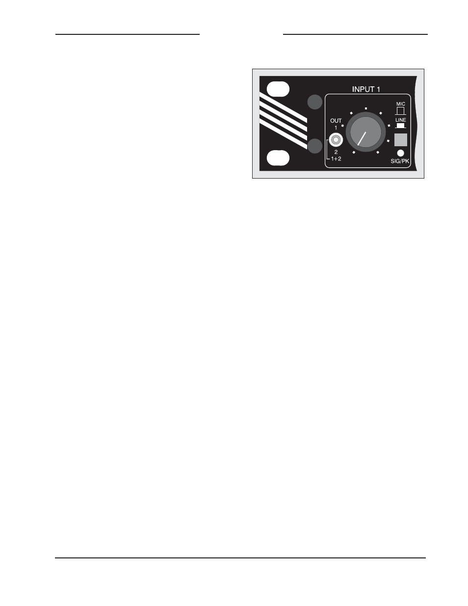
Input Sensitivity
The input circuitry is compatible with a
wide range of signal levels, as well as
being protected from overload. The mic/
line pushbutton is used to select the sensi-
tivity of the input. In the mic (out) position,
the expected nominal input level range
is –55 to –35 dBu. In the line (in) position,
a 43 dB pad is inserted into the circuit,
making the expected nominal input level
range –12 to +8 dBu.
Phantom Power
Depending on how the Model 742 was
configured at the time of installation,
12-volt phantom power may be available
to support condenser microphones. (A
single configuration jumper, located inside
the unit’s enclosure, is technician-selected
to enable or disable phantom power for
all four mic/line inputs.) If the unit is con-
figured for phantom power, it will only be
available when the input sensitivity switch
is set to its mic position. Phantom power
is not available in the line position. Note
that it’s normal for a slight “click” or “pop”
to be heard when moving the sensitivity
switch between the mic and line positions,
and vice versa. This noise, while slightly
annoying, will not harm the circuitry. It also
provides an aural indication that phantom
power is available. (It’s not a technical limi-
tation, it’s a feature!) If the unit is internally
configured not to supply phantom power,
no click will be heard when changing the
position of the switch.
Status LED
A dual-color LED acts as a user-
confidence indication of the overall signal
level in the mic/line input channel’s cir-
cuitry. The LED will light green as a signal
present indicator, showing that the input
signal, along with the gain of the input
preamplifier, is at least 18 dB below the
nominal internal operating level. The LED
Detail of front panel showing one mic/line input
channel